
A two-way automatic cutting and laminating machine

A laminating machine and cutting technology, applied in thin material processing, sending objects, transportation and packaging, etc., can solve the problems of lack of punching mechanism, inability to adjust the degree of film tension, film folds, etc., to speed up work efficiency. Effect

Active Publication Date: 2022-01-04
江苏博阳智能装备有限公司
View PDF9 Cites 0 Cited by
  • Summary
  • Abstract
  • Description
  • Claims
  • Application Information

AI Technical Summary

Problems solved by technology

[0006] The purpose of the present invention is to provide a two-channel automatic cutting and laminating machine to solve the problems of the inability to adjust the tension degree of the film, the lack of a punching mechanism and the easy wrinkling of the film in the above-mentioned background technology

Method used

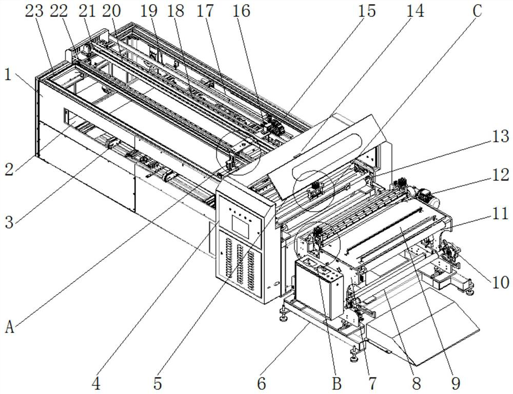
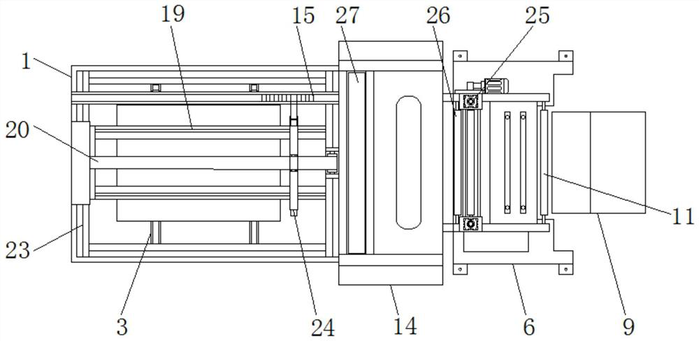
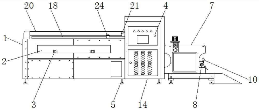

Image

  • A two-way automatic cutting and laminating machine
  • A two-way automatic cutting and laminating machine
  • A two-way automatic cutting and laminating machine

Examples


Embodiment Construction

[0024] The following will clearly and completely describe the technical solutions in the embodiments of the present invention with reference to the accompanying drawings in the embodiments of the present invention. Obviously, the described embodiments are only some, not all, embodiments of the present invention.

[0025] see Figure 1-6 , an embodiment provided by the present invention: a two-way automatic cutting and laminating machine, including a laminating box 1, a bottom plate 6 and a cutting and punching box 14, and the two ends of the top of the bottom plate 6 are vertically installed with mounting plates 7 , and the top of the side wall between the mounting plates 7 is horizontally installed with a top plate 9, the lower end of one side of the mounting plate 7 is horizontally installed with a main film rotating shaft 8 through the rotating shaft, and the lower ends of the mounting plates 7 at both ends of the main film rotating shaft 8 are provided with fixing mechanism...


PUM


Abstract

The invention relates to a two-channel automatic cutting and laminating machine, which includes a laminating box, a bottom plate and a cutting and punching box. Both ends of the top of the bottom plate are vertically installed with mounting plates, and the top of the side wall between the mounting plates is A top plate is installed horizontally, and the lower end of one side of the mounting plate is horizontally installed with a main film rotating shaft through the rotating shaft, and the lower ends of the mounting plate at both ends of the main film rotating shaft are provided with fixing mechanisms, and the side of the bottom plate far away from the main film rotating shaft is equipped with a cutting machine. A punching box, a control panel is installed at the middle position of the upper end of the front of the cutting punching box, and a film-coated box is installed on the side away from the bottom plate of the cutting punching box, and the middle position of the upper end of the front and back of the film-coating box is There are feed ports opened horizontally everywhere. In the present invention, by starting the operation of the first air cylinder, the second slide block is driven to slide in the second slideway, so as to drive the rise and fall of the adjustment roller, thereby completing the adjustment of the tension degree of the film.

Description

technical field [0001] The invention relates to the technical field of laminating machines, in particular to a two-pass automatic cutting and laminating machine. Background technique [0002] Film lamination, also known as "overplastic", "mounting glue", "film sticking", etc., refers to the use of transparent plastic film to be pasted on the surface of printed matter by hot pressing to protect and increase gloss. After the welding process, it is necessary to lay the EVA and the back plate for the second time, and punch holes according to the process requirements to ensure that the end of the bus bar protrudes from the hole after the film is covered. This process requires the use of a laminating machine instead of manual lamination. The traditional laminating machine There are still some problems, the specific problems are as follows: [0003] 1. Traditional devices of this type cannot adjust the tension of the film, the quality cannot be controlled, and cannot meet the tech...

Claims


Application Information

Patent Timeline
Patent Type & Authority Patents(China)
IPC IPC(8): B29C63/02B29C63/00B65H35/06
CPCB29C63/02B29C63/0004B65H35/06
Inventor 李松林
Owner 江苏博阳智能装备有限公司
Learn More