Construction structure and construction method for road reconstruction and upgrading of sponge city

A sponge city and road technology, applied in the directions of roads, roads, and botanical equipment and methods, can solve the problems of lack of "elasticity" ability, construction difficulty, and deep burial in heavy rainfall weather, so as to solve the heat island effect and improve the survival rate. rate, and the effect of avoiding road flooding

Pending Publication Date: 2020-04-07
GUANGDONG NO 1 CONSTRUCTION ENGINEERING CO LTD
View PDF2 Cites 1 Cited by
  • Summary
  • Abstract
  • Description
  • Claims
  • Application Information

AI Technical Summary

Problems solved by technology

[0003] At present, the road drainage system generally adopts the unified deployment and drainage method of traditional rainwater pipes, rainwater canals, pumping stations, etc. Among them, the rainwater pipes and rainwater canal facilities are hard facilities. Once completed, it is difficult to change their overall structure and direction. The construction is difficult, and the key is the lack of "elastic" ability to deal with heavy rainfall weather. The municipal roads in the central urban area are renovated and upgraded to sponge cities. Sponge city facilities can achieve the purpose of improving the original design drainage standard and removing rainwater from the road surface, and solve the problems of urban road waterlogging and heat island effect from the root, so as to achieve the effect of balanced discharge and storage of rainwater, and build a new type of town with sustainable development

Method used


Image

  • Construction structure and construction method for road reconstruction and upgrading of sponge city
  • Construction structure and construction method for road reconstruction and upgrading of sponge city
  • Construction structure and construction method for road reconstruction and upgrading of sponge city

Examples


Embodiment Construction

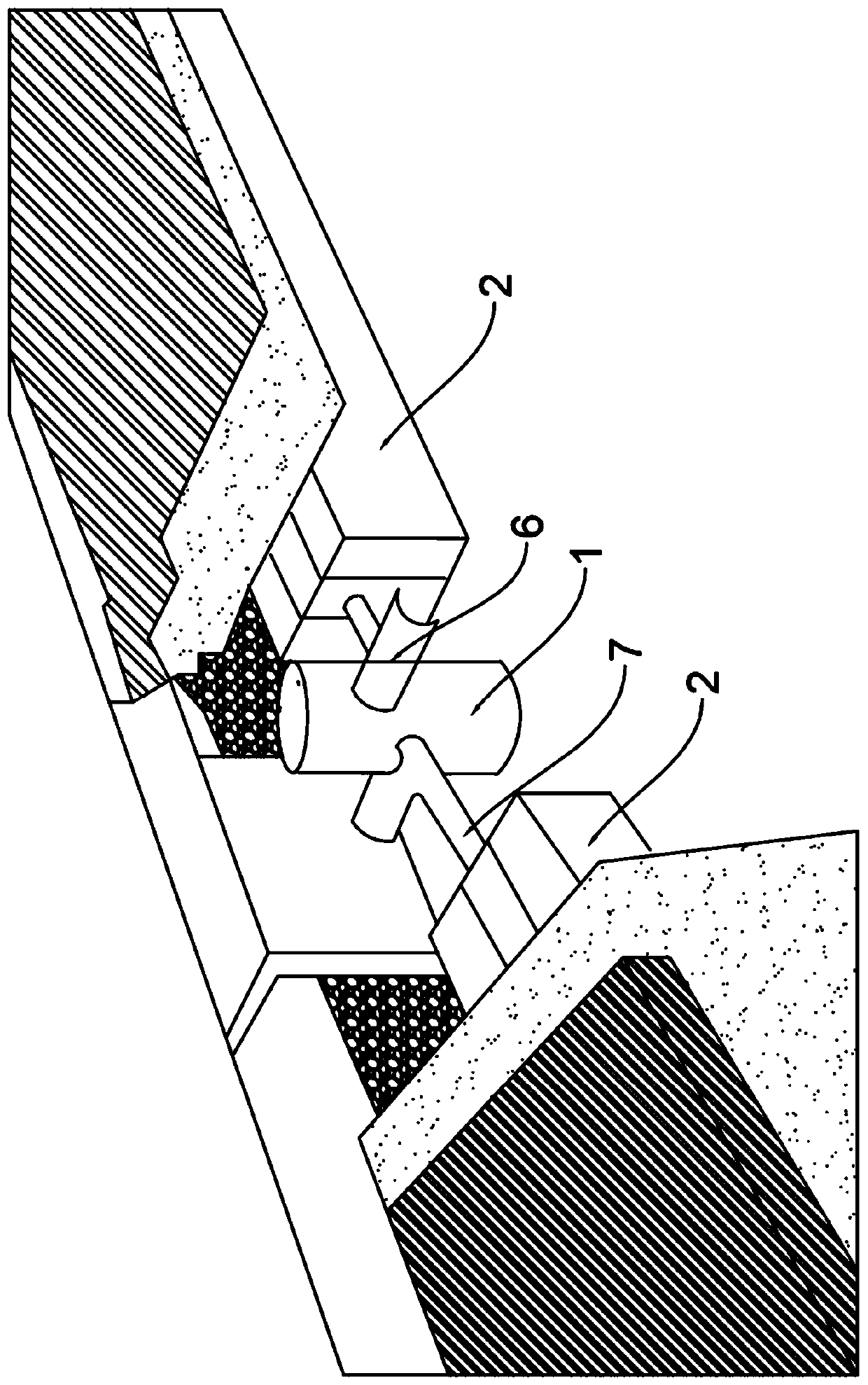
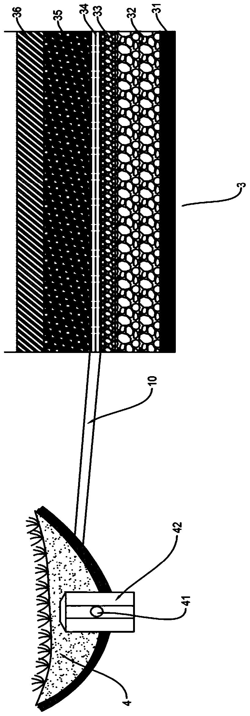
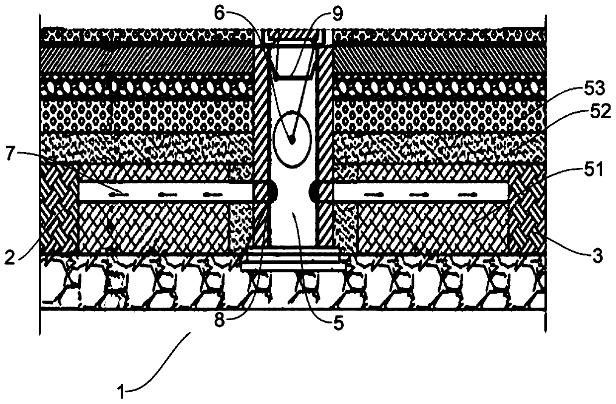
[0027] see Figure 1-3 As shown, the present invention relates to a construction structure for road reconstruction and upgrading of sponge cities, including tree pools, sidewalks, non-motor vehicle lanes, sunken green spaces, open curbs, porous fiber cotton modules 2, infiltration wells 1, grass planting ditch 3 and Rainwater garden 4, a sunken green space is provided on one side of the non-motorized road, a grass planting ditch 3 is provided on one side of the sidewalk, and a porous fiber cotton module 2 is provided between the tree ponds on both sides of the sidewalk and the non-motorized road. The infiltration well 1 includes a rainwater well 5 and a plain soil compaction layer 51, a gravel water purification layer 52 and a coarse sand layer 53 located around the rainwater well 5 from bottom to top, and an overflow pipe 6 communicating with it is provided in the middle of the rainwater well 5 One end of the overflow pipe 6 non-communicating rainwater well 5 is connected to ...


PUM


Abstract

The invention discloses a construction structure and a construction method for modifying and upgrading a road into a sponge city. The invention comprises a tree pool, a sidewalk, a non-motorized vehicle lane, a concave greenbelt, open kerbs, porous fiber cotton modules, seepage wells, grass planting ditches and rainwater gardens. The porous fiber cotton modules are arranged between the tree poolson the two sides of the sidewalk and the non-motorized vehicle lane; the seepage wells comprises rainwater wells, and rammed earth layers, gravel water purification layers and coarse sand layers which are sequentially arranged around the rainwater wells from bottom to top; an overflow pipe communicating with a catch basin is arranged in the middle of the catch basin; one end, not communicatingwith the catch basin, of the overflow pipe is connected with a municipal rainwater pipe network; a water guide pipe is arranged in a rammed earth layer, one end of the water guide pipe communicates with the porous cellucotton module, the other end of the water guide pipe communicates with the rainwater wells and provided with a stainless steel sewage intercepting cover, a rainwater garden is arranged on the sunken greenbelt, a blind pipe and an overflow well are arranged in the rainwater garden, the blind pipe communicates with the overflow well, and the overflow well is connected to a nearbymunicipal rainwater pipe network. According to the invention, the functions of unified storage, purification and discharge are realized.

Description

technical field [0001] The invention relates to the field of urban roads, in particular to a construction structure and construction method for road reconstruction and upgrading of sponge cities. Background technique [0002] "Sponge city" is a figurative metaphor, comparing the whole city to a "breathing" and "elastic" sponge. When it rains, the rainwater is absorbed and stored in the "sponge"; when water is needed, the "sponge" is squeezed to release the water, thereby realizing a virtuous cycle of water utilization. There are four main functions in building a sponge city, which can enhance urban drainage Waterlogging prevention ability, effective reduction of rainwater runoff pollution, promotion of rainwater resources utilization, mitigation of urban heat island effect. Through the absorption and storage of "sponge bodies" such as green spaces, artificial wetlands, rain gardens, and roof gardens, the time of rainwater discharge can be delayed, the total amount of storm ...

Claims


Application Information

Patent Timeline
Patent Type & Authority Applications(China)
IPC IPC(8): E01C5/04E01C15/00E01C11/00E01C11/22A01G9/02E03F1/00E03F5/04E03F5/042E03F5/06
CPCE01C5/04E01C15/00E01C11/00E01C11/221E01C11/224A01G9/02E03F1/002E03F5/0401E03F5/042E03F5/06Y02A10/30
Inventor 邱秉达钱阳邱伟武李云峰龙耘马剑勇黄旭青李贵喜冯燕华
Owner GUANGDONG NO 1 CONSTRUCTION ENGINEERING CO LTD
Why Eureka
Try Eureka