
Proppant conveying experimental device and method capable of obtaining proppant particle size distribution

A technology of particle size distribution and experimental device, which is applied in the direction of measuring device, particle size analysis, particle and sedimentation analysis, etc., to achieve the effect of overcoming the particle size distribution of test proppant

Active Publication Date: 2020-04-07
SOUTHWEST PETROLEUM UNIV
View PDF15 Cites 4 Cited by
  • Summary
  • Abstract
  • Description
  • Claims
  • Application Information

AI Technical Summary

Problems solved by technology

The above method or device only enriches the functions of the device in terms of pressure, temperature, variable fracture width, variable branch angle, etc., but the particle size distribution of proppant in fractures is a key factor affecting the final stimulation effect. Taking these factors into consideration, the patent application "Fracturing proppant particle size rapid evaluation device and application method" (CN109490155A), "Method for studying multi-stage fracturing proppant particle size and rock mass fracture characteristic parameters" (CN102749437A ) both proposed a device that uses particle screen sorting to obtain proppant particle size distribution information, but it is not used to obtain particle size distribution information in proppant migration and laying results

Method used


Image

  • Proppant conveying experimental device and method capable of obtaining proppant particle size distribution
  • Proppant conveying experimental device and method capable of obtaining proppant particle size distribution
  • Proppant conveying experimental device and method capable of obtaining proppant particle size distribution

Examples


Embodiment Construction

[0026] The present invention will be described in detail below in conjunction with the accompanying drawings.

[0027] see figure 1 .

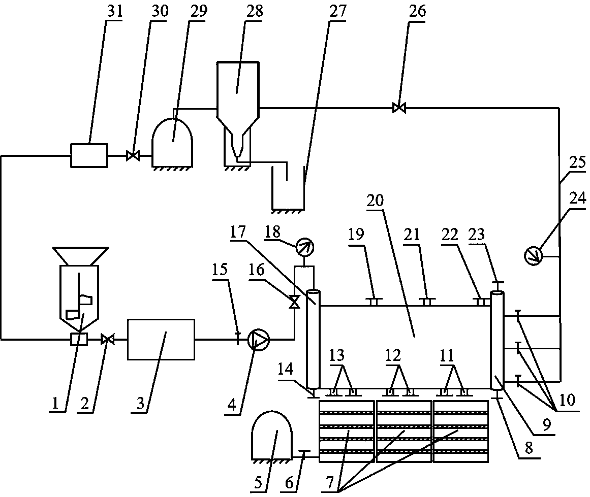
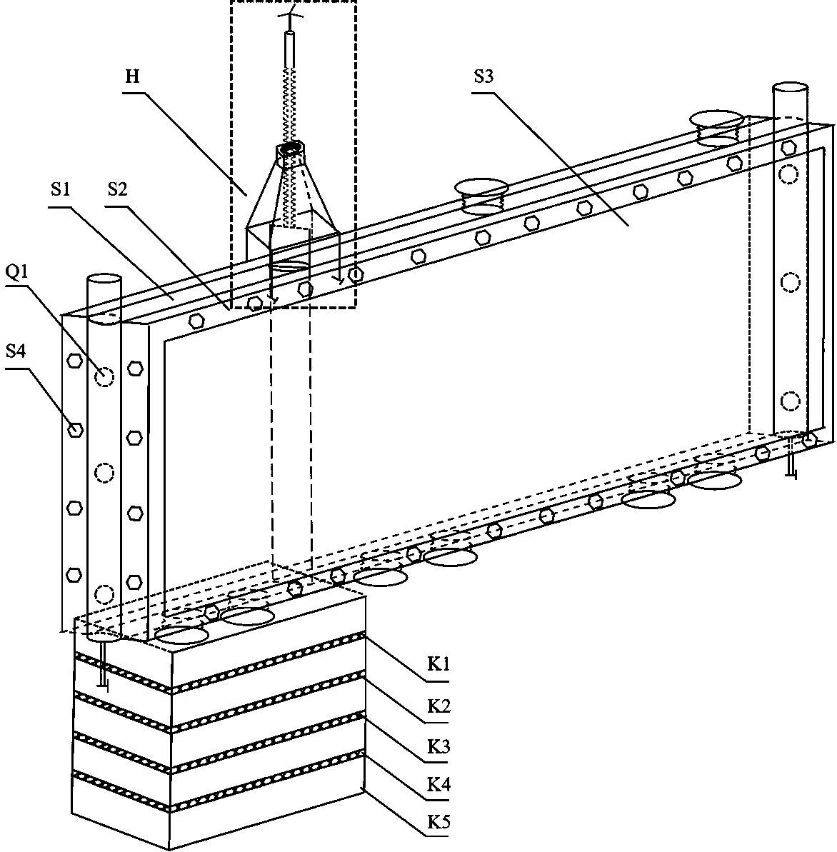
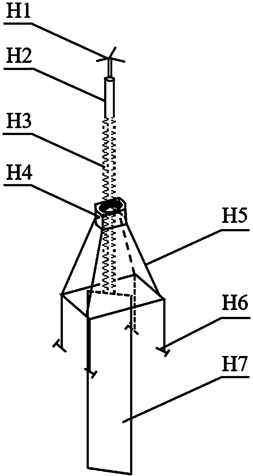
[0028] A proppant conveying experimental device capable of obtaining proppant particle size distribution, consisting of a sand mixing tank 1, a screw pump 3, a simulated inlet wellbore 17, a proppant conveying system 20, a particle size classification system 7, a mechanical division system H, and a simulated outlet The wellbore 9, the cyclone desander 28, the proppant recovery bucket 27, the liquid storage tank 29, and the liquid delivery pump 31 are composed.

[0029]The sand mixing tank 1 is connected to the simulated inlet shaft 17 through the shut-off valve 2 and the screw pump 3, and the pipeline between the screw pump and the simulated inlet shaft is sequentially provided with a regulating valve 15, a flow meter 4, a shut-off valve 16, and a pressure gauge 18; The above-mentioned proppant delivery system 20 is located between the simul...


PUM


Abstract

The invention relates to a proppant conveying experimental device and method capable of obtaining proppant particle size distribution. The device consists of a sand mixing tank 1, a screw pump 3, a simulated inlet shaft 17, a proppant conveying system 20, a particle size classification system 7, a mechanical segmentation system H, a simulated outlet shaft 9, a cyclone desander 28, a proppant recovery barrel 27, a liquid storage tank 29 and a liquid conveying pump 31. The method comprises the following steps of preparing a fracturing fluid, storing the fracturing fluid in the liquid storage tank, and pouring a proppant into the sand mixing tank; starting the liquid conveying pump and the sand mixing tank to uniformly mix the fracturing fluid and the proppant; enabling liquid carrying sand to enter a simulated fracture through the simulated inlet shaft, and then flow into the cyclone desander through the simulated outlet shaft and a pipeline; and opening a pore channel of a narrow plateat the upper part of the proppant conveying system, isolating the inner space of the simulated fracture by using the mechanical segmentation system, and acquiring the proppant particle size distribution information at different positions in the simulated fracture. A theoretical basis is provided for fracturing parameter design and proppant optimization, and the application prospect is wide.

Description

technical field [0001] The invention relates to the field of research on the law of proppant laying in the process of hydraulic fracturing, and in particular to a proppant delivery experimental device and method capable of obtaining the particle size distribution of the proppant. Background technique [0002] With the continuous reduction of conventional oil and gas reserves, people began to shift their focus to the development of unconventional oil and gas resources. Unconventional oil and gas refers to the fact that traditional technologies cannot obtain natural industrial production, and new technologies need to be used to improve reservoir permeability or fluid viscosity, etc. Oil and gas resources that can be exploited economically. At present, hydraulic fracturing is the most effective method to enhance the recovery of oil reservoirs. In the process of hydraulic fracturing, a large amount of fracturing fluid is injected into the well at a high enough rate to rupture th...

Claims


Application Information

Patent Timeline
IPC IPC(8): E21B43/267E21B49/00G01N15/02
CPCE21B43/267E21B49/00G01N15/0255
Inventor 郭建春李鸣张涛杨若愚孙堃穆轲帆曾先进
Owner SOUTHWEST PETROLEUM UNIV
Learn More