
Centralized ejection vacuum pump

A vacuum pump and collection technology, which is applied to jet pumps, pumps, non-displacement pumps, etc., can solve the problems of large pumping volume and difficulty, and achieve the effect of reducing pumping energy consumption, good effect and avoiding energy loss.

Active Publication Date: 2020-04-07
党祎贤
View PDF4 Cites 0 Cited by
  • Summary
  • Abstract
  • Description
  • Claims
  • Application Information

AI Technical Summary

Problems solved by technology

In this way, the goal of large pumping capacity and low energy consumption can be achieved, and the difficulties and problems of vacuum pumping in the prior art can be solved

Method used


Image

  • Centralized ejection vacuum pump
  • Centralized ejection vacuum pump
  • Centralized ejection vacuum pump

Examples


Embodiment Construction

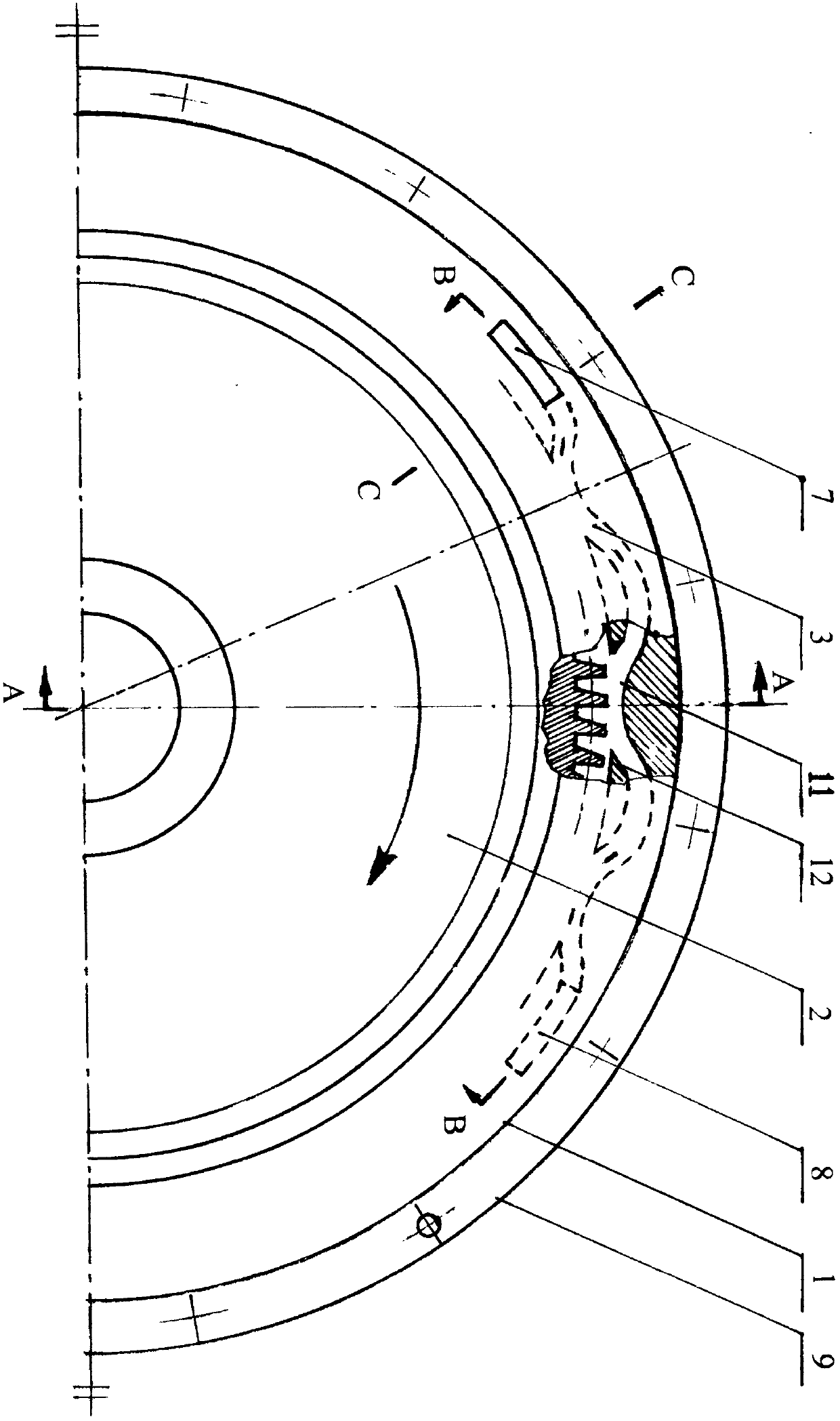
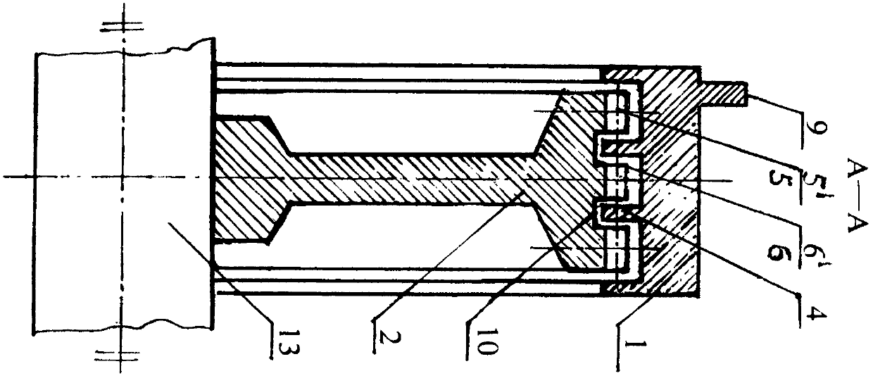
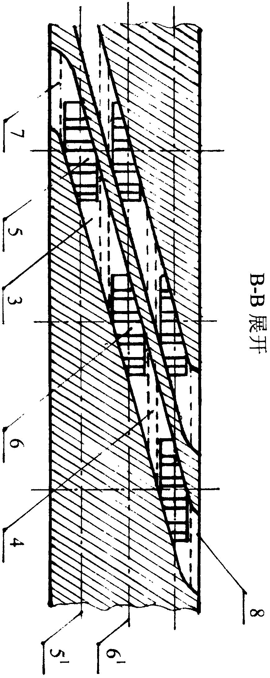
[0010] The ejector vacuum pump of the present invention is mainly composed of a pump body 1, a shaft 13, a gear 2, a bearing, a pump cover and the like. The inner cavity of the pump body 1 is provided with a spacer ring 4, which divides the inner cavity of the pump body into different injection chambers; at the same time, the pump body 1 is also provided with a pumping and discharging channel 3 with radial undulations and axial helical propulsion. The front end of the pumping channel 3 is an air suction port 7, the rear end is an exhaust port 8, and the middle part communicates with each ejection cavity step by step at a small diameter. The gas that enters the exhaust channel 3 through the suction port is first combined with the first-stage ejection cavity 5 1 Connected and in contact with the first-stage tooth row 5 of the gear 2, the pumped gas is pumped and pressurized and transported to the Secondary injection chamber 6 1 Contact and interact with the secondary tooth row...


PUM


Abstract

The invention provides a centralized ejection vacuum pump. The centralized ejection vacuum pump is composed of a pump body, a gear, a shaft, a bearing and a pump cover. Multiple stages ejection cavities are formed in an inner cavity of the pump body; and the pump body is internally provided with pumping and discharging channels which are fluctuated in the radial direction and spirally propelled inthe axial direction. A groove is formed in the gear, and the groove is matched with a spacer ring in the inner cavity of the pump body to form the multiple stages ejection cavities. The pumped gas entering the pumping and discharging channels through an air suction opening makes contact with and interacts with the gear rotating at a high speed, under the combined action of the low-pressure suction effect of rigid fluid, the mechanical pushing effect of gear teeth and the centrifugal force, the pumped gas is ejected to form directional flow and pressurized step by step, and high vacuum is obtained. The plurality of pumping and discharging channels which are relatively independent and work simultaneously are arranged in the pump body in the circumferential direction, so that a large pumpingamount is obtained. According to the centralized ejection vacuum pump, large air exhaust amount and high vacuum can be obtained under the condition of low energy consumption.

Description

technical field [0001] The invention relates to a method for extracting gas from a sealed container to obtain a vacuum, in particular to an ejector vacuum pump. Background technique [0002] Vacuum is often needed in scientific research and industrial production to provide ideal environmental conditions for experiments and production, which requires the use of vacuum pumps. For occasions that require large pumping capacity (such as vacuum refining outside the steelmaking furnace), steam jet pumps and volumetric mechanical pumps (such as Roots pumps, screw pumps, rotary vane pumps, etc.) are currently mainly used. For steam jet pumps, on the one hand, the acquisition of steam consumes a lot of energy; on the other hand, as the number of pumping stages increases, the amount of steam consumed increases step by step; at the same time, the turbulent flow loss of the airflow is also very large. In short, this method of exchanging high energy consumption for high temperature, high...

Claims


Application Information

Patent Timeline
Patent Type & Authority Applications(China)
IPC IPC(8): F04F5/04F04F5/44
CPCF04F5/04F04F5/44F04C25/02C21C7/10
Inventor 党祎贤
Owner 党祎贤
Learn More