A device for measuring the dld of a crystal oscillator element

A technology of components and crystal oscillators, which is applied in the application field of piezoelectric crystal components, can solve problems affecting the DLD accuracy of crystal oscillator components, high labor intensity of staff, and sticky dust on pins, so as to avoid moisture ingress, improve measurement efficiency, and reduce The effect of labor intensity

Active Publication Date: 2022-05-13
HUNAN JIAYEDA ELECTRONICS
View PDF9 Cites 0 Cited by
  • Summary
  • Abstract
  • Description
  • Claims
  • Application Information

AI Technical Summary

Problems solved by technology

[0003] When the crystal oscillator is measured, the pins of the crystal oscillator need to be in contact with the measuring device to form a circuit. When the crystal oscillator is loaded, it is generally done manually. After a crystal oscillator is measured, it needs to be removed and replaced with a new crystal oscillator. , it may be necessary to manually take the crystal oscillator body repeatedly for loading and unloading during measurement, the labor intensity of the staff is high, and the measurement efficiency may be low; when measuring the crystal oscillator components, the pins may be covered with dust, which may affect the crystal oscillator. Accuracy of Component DLD Measurements

Method used


Image

  • A device for measuring the dld of a crystal oscillator element
  • A device for measuring the dld of a crystal oscillator element
  • A device for measuring the dld of a crystal oscillator element

Examples


Embodiment Construction

[0032] The following will clearly and completely describe the technical solutions in the embodiments of the present invention with reference to the accompanying drawings in the embodiments of the present invention. Obviously, the described embodiments are only some, not all, embodiments of the present invention. Based on the embodiments of the present invention, all other embodiments obtained by persons of ordinary skill in the art without making creative efforts belong to the protection scope of the present invention.

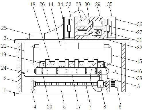
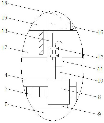
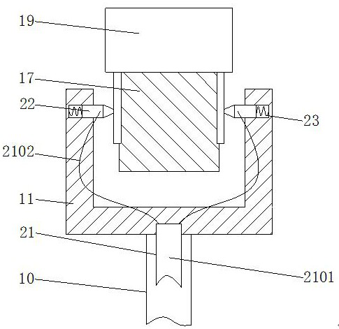
[0033] see Figure 1-7 As shown, a device for measuring the DLD of a crystal oscillator component includes a base plate 1, a sample strip 17, a first connection line 21, a second connection line 26, a horizontal driving structure and a clamping structure, and the base plate 1 is fixed through a support rod 2 with top plate 3;

[0034] The horizontal drive structure includes an open housing 4 and a slider 9 fixedly installed on the top of the bottom plate 1, t...


PUM


Abstract

The invention discloses a device for measuring the DLD of a crystal oscillator, which comprises a bottom plate, a support rod, a top plate, an open shell, a guide rail, a servo motor, a screw, a ball nut, a slider, a connecting bar, a U-shaped bar, a connecting block, a wool Brush, electric push rod, connecting rod, pressing block, sample strip, rubber block, crystal oscillator body, cleaning comb, first connecting wire, plastic rubber sleeve, wire, contact head, spring, limit ring, wire storage box, rotating shaft , reel, torsion spring, second connecting wire, fixed box, circuit board, arbitrary waveform generator, digital oscilloscope, output interface, high-frequency non-inductive adjustable resistor, digital power meter, fan, first filter, Desiccant layer, exhaust fan, second filter, microcontroller and handle. In the present invention, multiple crystal oscillator bodies can be loaded at one time through the sample strip, and the contact head used for measurement is driven to move through the horizontal driving structure, so that the crystal oscillator bodies can be measured one by one, thereby preventing staff from repeatedly taking the crystal oscillator body for loading and unloading.

Description

technical field [0001] The invention relates to a device for measuring DLD, in particular to a device for measuring DLD of a crystal oscillator element, and belongs to the technical field of piezoelectric crystal element applications. Background technique [0002] As a type of basic electronic components, crystal oscillator components are widely used in various analog or digital circuits to provide high-stability clock signals for electronic circuits; the DLD characteristics of crystal oscillator components are crucial to the stability of crystal oscillator components during use , which reveals the characteristics of the resonant resistance of the crystal element as a function of the excitation level and the dependence of the excitation level. [0003] When the crystal oscillator is measured, the pins of the crystal oscillator need to be in contact with the measuring device to form a loop. When loading the crystal oscillator, it is generally done manually. After a crystal os...

Claims


Application Information

Patent Timeline
Patent Type & Authority Patents(China)
IPC IPC(8): G01R31/01G01R1/04H05K7/20
CPCG01R31/01G01R1/0425G01R1/0416H05K7/20172
Inventor 何龙施小罗
Owner HUNAN JIAYEDA ELECTRONICS
Why Eureka
Try Eureka