Uplink control information transmission method, terminal and network equipment

A transmission method and technology for controlling information, applied in the field of communication, can solve problems such as poor PUCCH resource indication effect and the like

Pending Publication Date: 2020-04-07
VIVO MOBILE COMM CO LTD
View PDF5 Cites 1 Cited by
  • Summary
  • Abstract
  • Description
  • Claims
  • Application Information

AI Technical Summary

Problems solved by technology

[0003] Embodiments of the present invention provide a UCI transmission method, termi...

Method used


Image

  • Uplink control information transmission method, terminal and network equipment
  • Uplink control information transmission method, terminal and network equipment
  • Uplink control information transmission method, terminal and network equipment

Examples


Embodiment approach

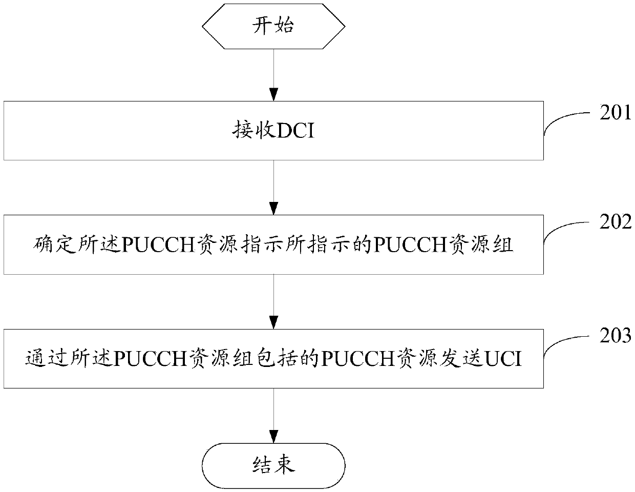
[0081] As an optional implementation manner, the PUCCH resource group indicated by the PUCCH resource indication includes:

[0082] The PUCCH resource indicates an implicitly indicated PUCCH resource group, and the PUCCH resource group includes:

[0083] The PUCCH resource indicates a corresponding first PUCCH resource;

[0084] The second PUCCH resource matched by the first PUCCH resource.

[0085] Wherein, the first PUCCH resource may be one or more PUCCH resources, and the second PUCCH resource may also be one or more PUCCH resources. In addition, the second PUCCH resource matched by the above-mentioned first PUCCH resource may be that there is a certain relationship between the configuration parameters of the first PUCCH resource and the second PUCCH resource, for example: the time domain is adjacent, or the frequency domain is adjacent, or the frequency domain is the same, But the time domain is adjacent and so on.

[0086] In this implementation manner, the PUCCH reso...

Embodiment 1

[0115] In this embodiment, each ARI indication corresponds to n PUCCH resources.

[0116]In this embodiment, it is possible to modify the current protocol standard. For PUCCH RESET 1 / 2 / 3, PUCCH RESET is allowed to configure 8n resources (the current Rel-15NR protocol only allows configuration of 8 resources), and each ARI indication corresponds to n PUCCH resources (n≥2). Taking n=2 as an example, refer to Table 1, which will not be repeated here.

Embodiment 2

[0118] In this embodiment, a corresponding PUCCH Resource is configured for each ARI indication.

[0119] Multiple PUCCH Resources are specified for each ARI indication, and the numbers of PUCCH Resources indicated by different ARIs may be the same or different.

[0120] The advantage of doing this is that the base station can use the ARI to dynamically modulate the number of resources for the terminal to use the PUCCH to transmit UCI according to the occupancy of the channel.

[0121] When the channel is relatively busy or the network load is relatively large, use ARI to indicate more PUCCH resources;

[0122] When the channel is relatively idle or the load of the network is relatively small, the ARI is used to indicate less PUCCH resources.

[0123] In this embodiment, it can be based on the modification of the existing protocol signaling, as follows:

[0124] Add PUCCH_resource_indicator (that is, ARI) to the PUCCH_resource mapping table, and for the value corresponding t...


PUM


Abstract

Provided are an uplink control information transmission method, a terminal and a network device, the method comprising: receiving DCI, the DCI comprising a physical uplink control channel PUCCH resource indication; determining a PUCCH resource group indicated by the PUCCH resource indication, wherein the PUCCH resource group comprises a plurality of PUCCH resources, and the PUCCH resource group comprises a plurality of PUCCH resources; or the PUCCH resource group is one PUCCH resource group selected from at least one first PUCCH resource group and at least one second PUCCH resource group according to the PUCCH resource indication; wherein the first PUCCH resource group comprises a plurality of PUCCH resources, and the second PUCCH resource group comprises one PUCCH resource; and sending the UCI through the PUCCH resources included in the PUCCH resource group. According to the embodiment of the invention, the indication effect of PUCCH resources can be improved.

Description

technical field [0001] The present invention relates to the field of communication technologies, and in particular to an uplink control information (Uplink Control Information, UCI) transmission method, a terminal and a network device. Background technique [0002] In a communication system, a terminal often needs to send UCI to a network device, for example, to feed back a Hybrid Automatic Repeat Request ACK (HARQ-ACK). Wherein, sending UCI is sent on physical uplink control channel (Physical Uplink Control Channel, PUCCH) resources, and the network device in the current communication system can only indicate one PUCCH resource under any circumstances, it can be seen that the number of PUCCH resources in the current communication system Poor indication. Contents of the invention [0003] Embodiments of the present invention provide a UCI transmission method, a terminal and a network device, so as to solve the problem of poor indication effect of PUCCH resources. [0004...

Claims


Application Information

Patent Timeline
IPC IPC(8): H04W72/04H04L5/00
CPCH04L5/0053H04L5/0055H04W72/23
Inventor 沈晓冬
Owner VIVO MOBILE COMM CO LTD
Why Eureka
Try Eureka