Point type optical fiber smoke-sensing fire detector with built-in spectroscopic optical fiber as signal indication

A fire detector and signal indication technology, applied in instruments, measuring devices, scientific instruments, etc., can solve problems such as hidden safety hazards, increase labor costs, increase production costs, etc., and achieve the effect of reducing length, saving labor costs, and saving light sources

Pending Publication Date: 2019-07-30
深圳晶点光科有限公司
View PDF0 Cites 1 Cited by
  • Summary
  • Abstract
  • Description
  • Claims
  • Application Information

AI Technical Summary

Problems solved by technology

[0002] At present, most of the smoke detectors or sensors used for automatic fire alarm at home and abroad are photoelectric, ion or infrared beam (laser) line detectors, etc., and they all use electrical signals and electronic components, so they all have electrical signals. , Electronic components cause potential safety hazards and easy aging defects. For this reason, a new smoke detector has appeared in the prior art, that is, an optical fiber smoke detector, which uses optical fiber sensing technology to detect smoke changes. However, in its application, when an externally displayed signal indicator light is set in order to comply with national regulations, it is necessary to add a separate signal indicating light source and a separate signal indicating optical fiber in addition to the optical fiber smoke detector. One end of the optical fiber communicates with the signal indicating light source, and the other end passes through a long-distance pipe and leads to the appearance of the optical fiber smoke detector to indicate the working status of the optical fiber smoke detector, which not only increases the production cost of the device, but also Added a lot of labor costs—mainly cumbersome and expensive long-distance pipe threading operations

Method used


Image

  • Point type optical fiber smoke-sensing fire detector with built-in spectroscopic optical fiber as signal indication
  • Point type optical fiber smoke-sensing fire detector with built-in spectroscopic optical fiber as signal indication
  • Point type optical fiber smoke-sensing fire detector with built-in spectroscopic optical fiber as signal indication

Examples


Embodiment 1

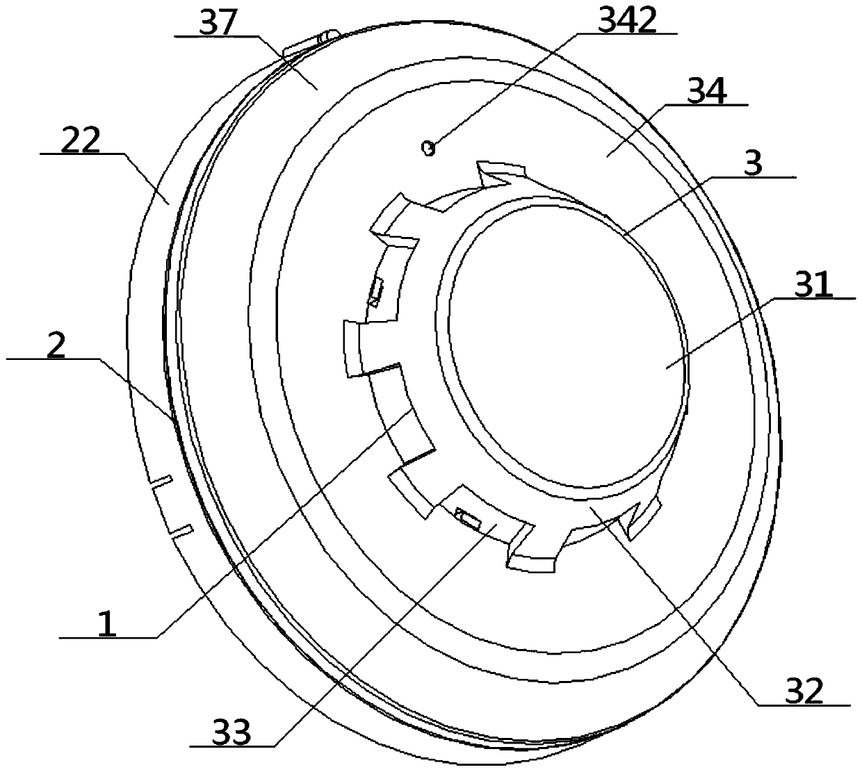
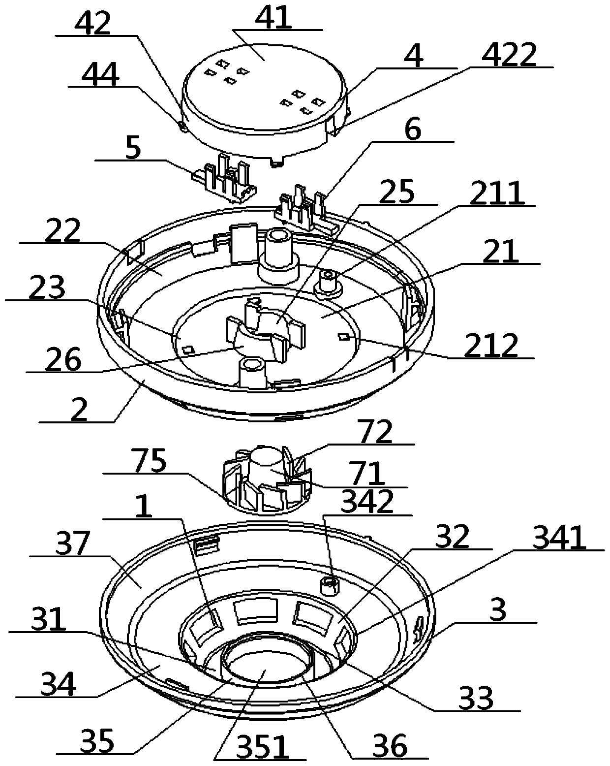
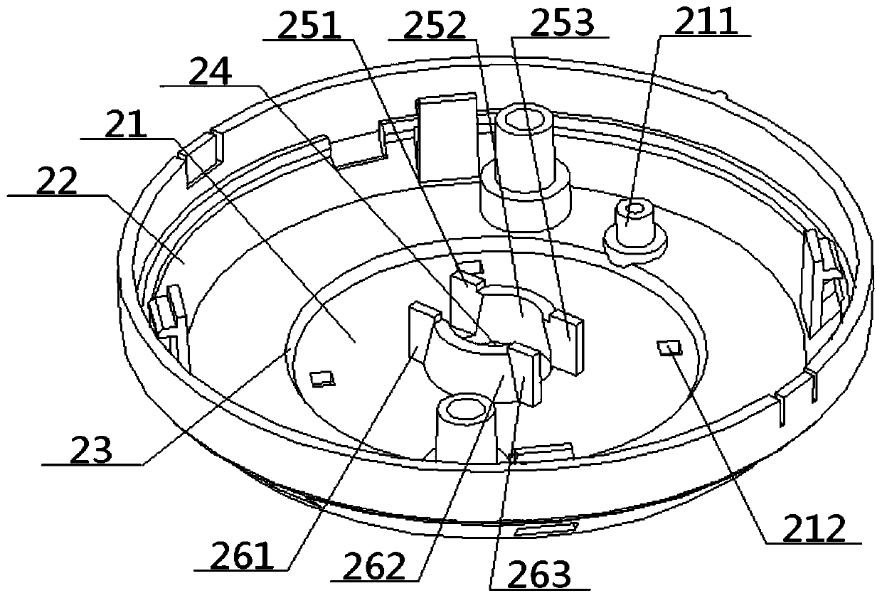
[0057] see Figure 1 to Figure 13 , a point-type optical fiber smoke fire detector with a built-in spectroscopic optical fiber for signal indication, including a base shell 2 and a bottom shell 3 both of which are hollow structures, and the base shell 2 includes a base plate 21 and is connected to its surroundings The base side wall 22, the base side wall 22, the base plate 21 surround a base shell cavity 23, the bottom shell 3 includes a bottom shell plate 31 and a bottom side wall 32, one end of the bottom side wall 32 is connected to The bottom surface of the base plate 21 is connected, and the other end of the bottom side coaming plate 32 is connected with the surroundings of the bottom shell plate 31. The bottom side coaming plate 32 and the bottom shell plate 31 form a bottom shell cavity 33, and the bottom side coaming plate 32 is provided with a smoke inlet 1 communicating with the bottom shell cavity 33; the point-type optical fiber smoke fire detector also includes a...

Embodiment 2

[0059] Basic content is the same as embodiment 1, the difference is:

[0060] The bottom shell 3 also includes a bottom shell ring plate 34, and the middle part of the bottom shell ring plate 34 is provided with a bottom shell ring hole 341 in contact with the bottom shell cavity 33, and the bottom surface of the bottom shell ring plate 34 is close to the bottom shell ring. The hole 341 is connected to the top of the bottom side panel 32, the top surface of the bottom shell ring plate 34 is connected to the bottom surface of the base plate 21, and the bottom shell ring plate 34 is provided with a signal hole corresponding to the base shell signal hole 211. The signal hole 342 of the bottom case.

Embodiment 3

[0062] Basic content is the same as embodiment 1, the difference is:

[0063] The receiving optical fiber clamping part 6 includes a receiving fixed seat 62 and a receiving movable seat 63, the bottom of the receiving fixed seat 62 is connected with the box top plate 41, and a receiving half groove 620 is opened in the top of the receiving fixed seat 62. The receiving movable seat 63 includes a receiving bottom plate 64, a receiving supporting plate 65, and receiving inner splints 66 and receiving outer splints 67 facing to each other. The bottom ends of 65 are connected, and the top of receiving supporting plate 65 is provided with supporting plate half groove 651, and the tops of receiving inner clamping plate 66 and receiving outer clamping plate 67 extend upwards, receiving inner clamping plate 66 and receiving outer clamping plate 67 to form a The clamping column cavity 68 coaxial with the supporting plate half-groove 651 , the clamping column cavity 68 , the supporting p...


PUM


Abstract

The invention discloses a point type optical fiber smoke-sensing fire detector with a built-in spectroscopic optical fiber as signal indication. The point type optical fiber smoke-sensing fire detector with a built-in spectroscopic optical fiber as the signal indication comprises a base shell, a bottom shell and a sensing box; wherein in the sensing box, one end of the box side body is connected to the box top plate, and the other end of the box side body is connected to the base bottom plate in the base shell; a smoke guiding port is opened in the middle of the base bottom plate; in the innercavity of the box, a clamping spacer region between an incident fiber clamping portion and a receiving fiber clamping portion is connected with a smoke inlet in the bottom shell through the smoke guiding port and a bottom shell cavity; an incident / receiving fiber clamping groove is separately formed in the inside of the incident / receiving fiber clamping portion; the depth of the incident fiber clamping groove is smaller than the depth of the receiving fiber clamping groove; the receiving fiber clamping groove includes a receiving fiber clamping cavity and a signal indicating fiber clamping cavity which are communicated; and a base shell signal hole communicated with the signal indicating fiber clamping cavity is formed on the base bottom plate. The design can not only realize the smoke sensing of the optical fiber, but also realize the built-in effect of the signal indicating fiber and reduce the application cost.

Description

technical field [0001] The invention relates to a smoke alarm device, in particular to a point-type optical fiber smoke fire detector with a built-in spectroscopic optical fiber for signal indication, which is particularly suitable for reducing the application cost through the built-in signal indication optical fiber. Background technique [0002] At present, most of the smoke detectors or sensors used for automatic fire alarm at home and abroad are photoelectric, ion or infrared beam (laser) line detectors, etc., and they all use electrical signals and electronic components, so they all have electrical signals. , Electronic components cause potential safety hazards and easy aging defects. For this reason, a new smoke detector has appeared in the prior art, that is, an optical fiber smoke detector, which uses optical fiber sensing technology to detect smoke changes. However, in its application, when an externally displayed signal indicator light is set in order to comply wit...

Claims


Application Information

Patent Timeline
Patent Type & Authority Applications(China)
IPC IPC(8): G01N21/01G01N21/53
CPCG01N21/01G01N21/53
Inventor 张森
Owner 深圳晶点光科有限公司
Why Eureka
Try Eureka