Equipment and method for realizing dual-energy scanning by using flying focal spot switching and X-ray filter

An X-ray and filter technology, applied in the field of medical imaging, can solve the problem that it is difficult to realize the combination of high and low KV scanning mode and flying focus scanning mode, and achieve the effect of simple and practical control mode and manufacturing cost

Pending Publication Date: 2020-04-10
FMI MEDICAL SYST CO LTD
View PDF5 Cites 6 Cited by
  • Summary
  • Abstract
  • Description
  • Claims
  • Application Information

AI Technical Summary

Problems solved by technology

This is beyond the reach of the current slip ring design. Even with 16-bit encoding, 256 rows of detectors, and a sampling rate of 2048 per circle, a slip ring bandwidth of 28.1Gbps is required. It is almost difficult to achieve high and low KV in cardiac scanning. Combination of scanning mode and flying focus scanning mode

Method used


Image

  • Equipment and method for realizing dual-energy scanning by using flying focal spot switching and X-ray filter
  • Equipment and method for realizing dual-energy scanning by using flying focal spot switching and X-ray filter
  • Equipment and method for realizing dual-energy scanning by using flying focal spot switching and X-ray filter

Examples


Embodiment 1

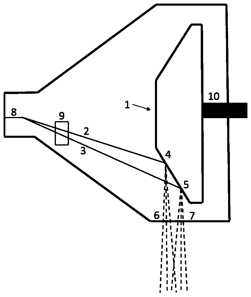
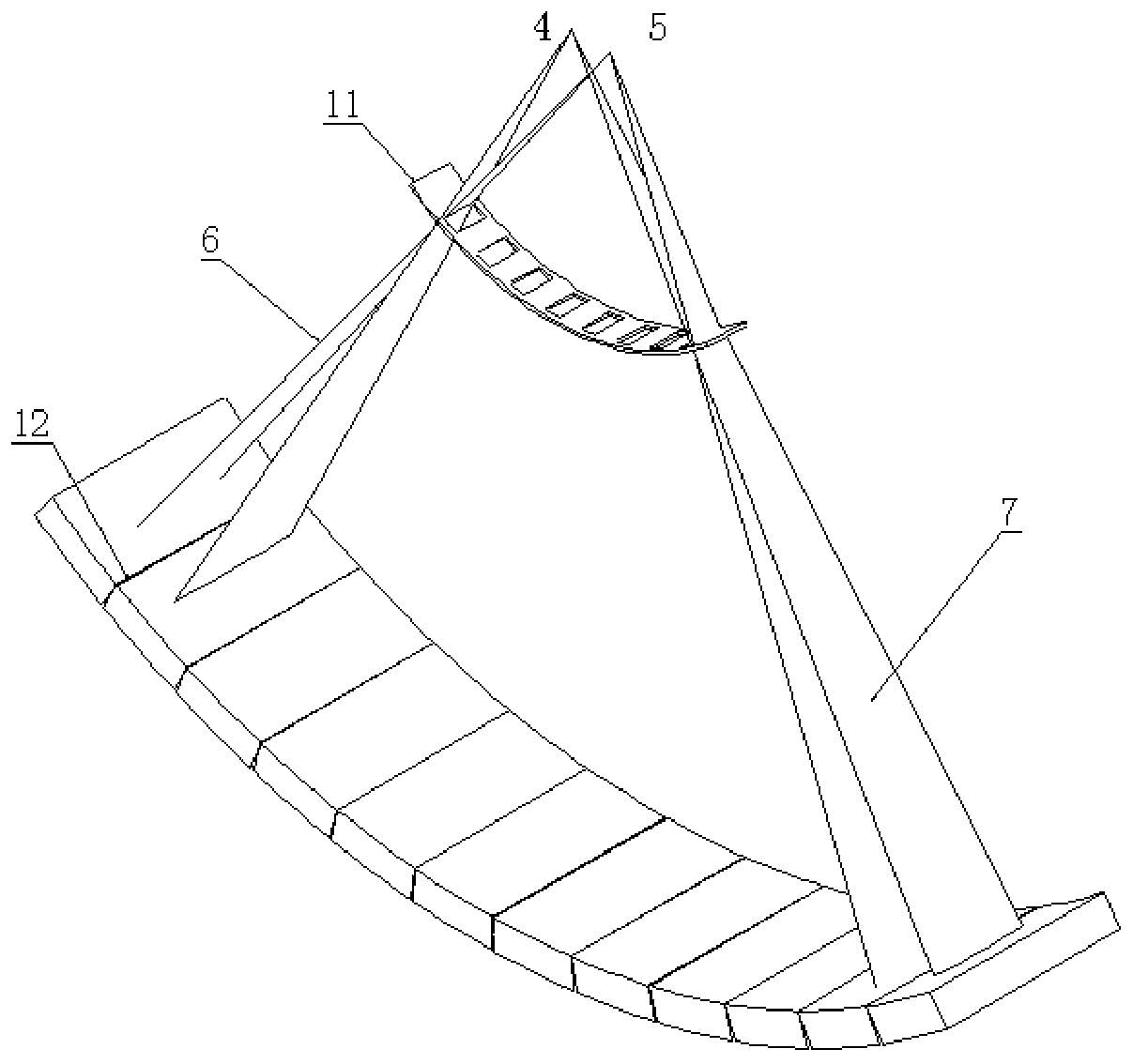
[0045] Such as figure 2 , image 3 , Figure 4 with Image 6 As shown, a device for dual-energy CT scanning using femtofocus switching and X-ray filter grid combination in this embodiment includes an X-ray tube, which can emit two X-ray beams from two different X-ray focal points; X The ray filter is installed between the CT detector array and the X-ray focal point (it can be installed inside or outside the tube, and can be installed in the front collimator of the CT system), absorbing low-energy or high-energy X-rays, and setting There are periodically distributed slits, which are used to directly transmit X-rays; X-rays irradiated by one of the X-ray focal points make the X-rays of the odd channels pass directly through the filter without attenuation, and the X-rays of the even channels are filtered The attenuation of the material of the device changes the X-ray energy spectrum. The X-rays irradiated by another X-ray focus make the X-rays of the even channels pass direc...

Embodiment 2

[0054] This example refers to image 3 An example in the Z direction of a solution according to the invention is provided.

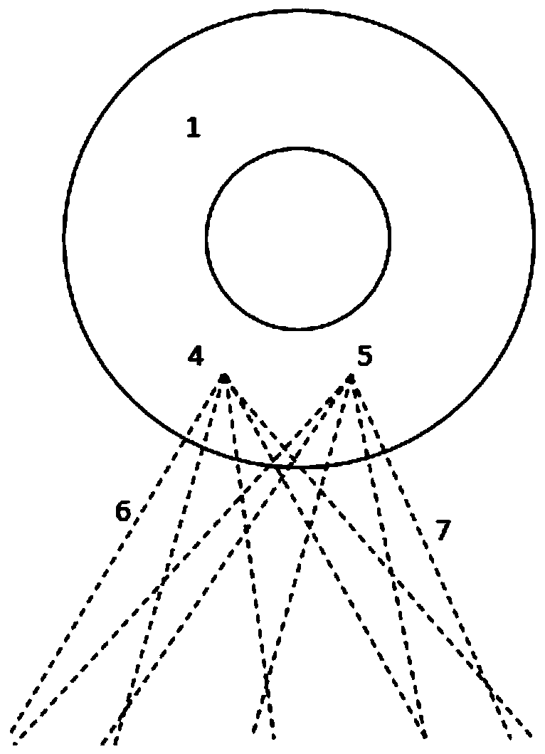
[0055] Such as figure 1 , Figure 5 , Figure 7 with Figure 8 As shown, a device for dual-energy CT scanning using femtofocus switching and X-ray filter grid combination in this embodiment includes an X-ray tube, which can emit two X-ray beams from two different X-ray focal points; X The ray filter, installed between the CT detector array and the X-ray focus, absorbs low-energy or high-energy X-rays, and is provided with periodically distributed slits, which are used to directly transmit X-rays; one of the X-ray focuses emits The X-ray beam passes through the slit and irradiates the odd channel of the detector, and the X-ray beam emitted by another X-ray focus passes through the slit and irradiates the even channel of the detector; The filter adopts X-direction grid.

[0056] The schematic diagram of the section of the X-ray tube is shown in figu...


PUM


Abstract

The invention provides equipment and a method for realizing dual-energy scanning by using flying focal spot switching and an X-ray filter, and relates to the technical field of medical images. The equipment comprises an X-ray bulb tube and an X-ray filter; the X-ray bulb tube can emit two X-ray beams from two different X-ray focal points; the X-ray filter is arranged between a CT detector array and the X-ray focal points and is provided with slits which are distributed periodically. According to the X-ray beam emitted by one of the X-ray focal points, X-rays of odd-numbered channels directly pass through the filter without attenuation, and X-rays of even-numbered channels are attenuated through a filter material, and the X-ray energy spectrum is changed. According to the X-ray beam emittedby the other X-ray focal point, X-rays of even-numbered channels directly pass through the filter without attenuation, and X-rays of odd-numbered channels are attenuated through the filter material,and the X-ray energy spectrum is changed. Therefore, the purpose of dual-energy CT scanning can be achieved. The scanning mode can combine a flying focal spot mode and an energy spectrum CT scanning mode when a heart is rapidly scanned, and requirements on the bandwidth of a slip ring is not high.

Description

technical field [0001] The invention relates to the technical field of medical imaging, in particular to a device and method for dual-energy scanning realized by femto-focus switching and X-ray filters. Background technique [0002] The main components of the third-generation CT system include Tube (ball tube), Collimator (beam limiter), and Detector (detector). The X-ray tube emits X-rays, which are limited by a beam limiter to form a cone-shaped beam. The cone-shaped light beam is irradiated on the detector and converted into an electrical signal by the detector, and then converted into digital information by the data acquisition and conversion unit and stored in the image processing system. The image processing system generates images and displays them on the monitor through a series of correction algorithms and image reconstruction algorithms. In terms of cost and technology maturity, the mainstream detectors use a number of detector modules arranged on an arc or polyg...

Claims


Application Information

Patent Timeline
Patent Type & Authority Applications(China)
IPC IPC(8): A61B6/03A61B6/00
CPCA61B6/482A61B6/035A61B6/4035A61B6/54A61B6/5235
Inventor 王斌王遥法徐琴
Owner FMI MEDICAL SYST CO LTD
Why Eureka
Try Eureka