Riveting process of u-shaped beam
A crossbeam and U-shaped technology, which is applied in the field of U-shaped crossbeam riveting technology, can solve the problems of time-consuming and laborious detection, falling out of the crossbeam 2, and limited reduction of the opening width of the groove 11, so as to improve the assembly quality.
- Summary
- Abstract
- Description
- Claims
- Application Information
AI Technical Summary
Problems solved by technology
Method used
Image

Examples
Embodiment Construction
[0025] The present invention will be further described in conjunction with the specific embodiments.
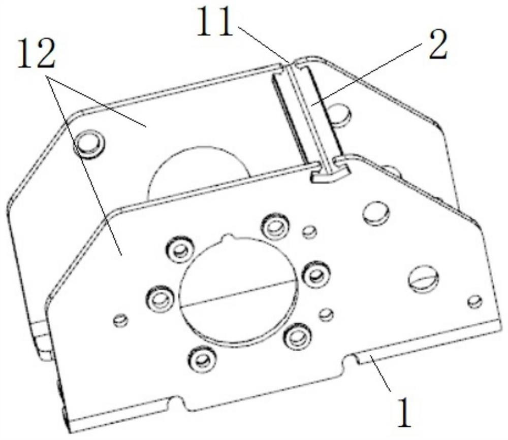
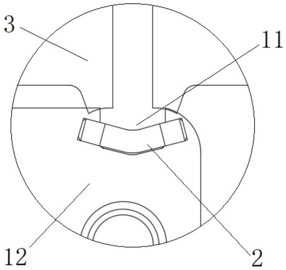
[0026] like image 3 with Figure 4 As shown, a U-shaped beam riveting process of the present invention includes:
[0027] 1 tape strip strip: For the metal tape, the contour is diced without completely cut, and two recess 11 used to assemble the beam 2;
[0028] 2 Material U-bending: U-shaped bent is performed as a reference feed surface as a reference surface, forming two facing surface 12 of each other;
[0029] 3U-shaped parts falling: cutting the main body of the U-shaped parts 1 from the material tape;
[0030] 4 Beam assembly: the bayonet card on both ends of the beam 2 into the groove 11;
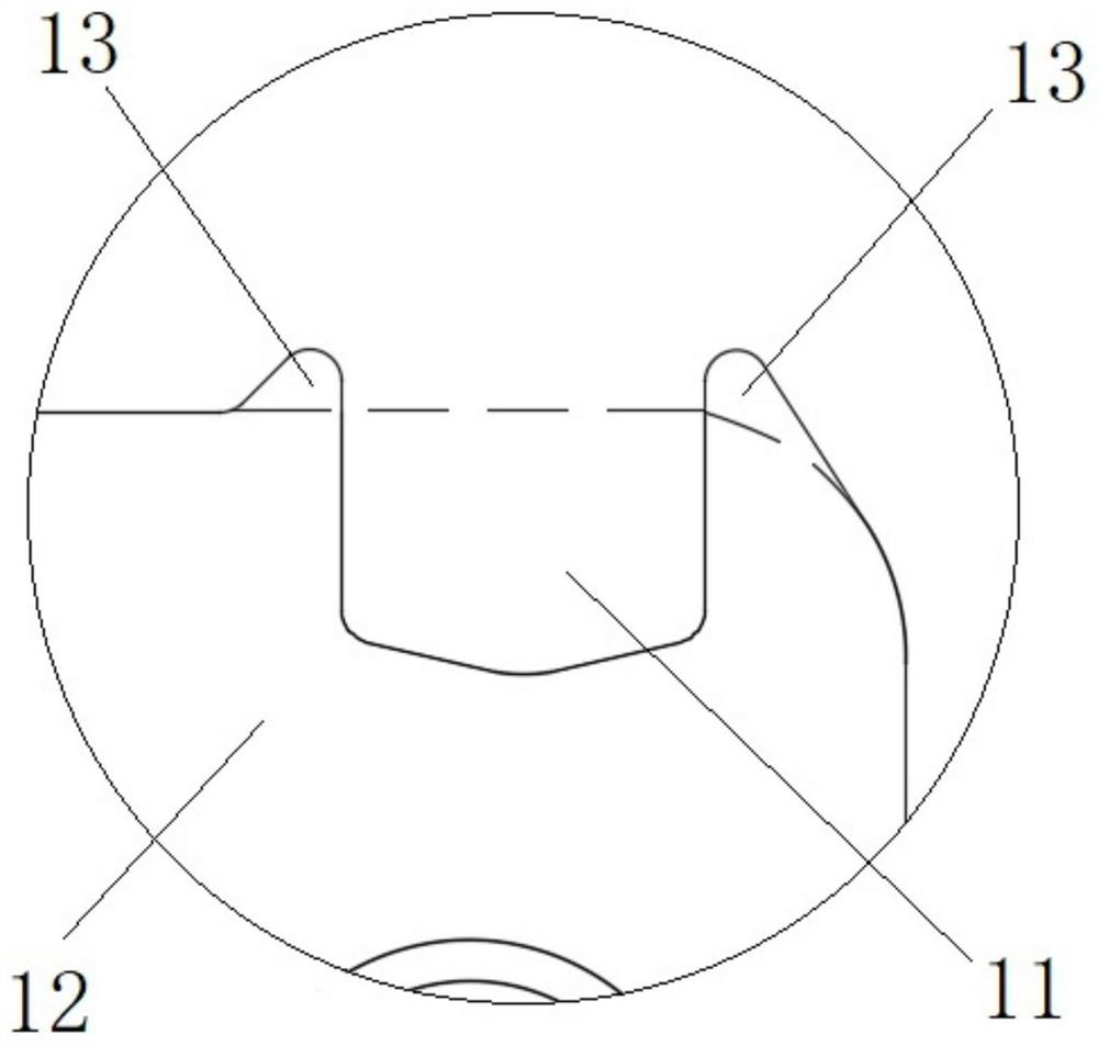
[0031] 5 riveting: The U-shaped member 1 groove 11 containing the beam 2 is placed upward in the riveting machine, and the inlet edge of the groove 11 is pressed and deformed, and the beam 2 is stuck;
[0032] The shape of the tape strip section increases the projection portion 13 on bot...
PUM
 Abstract
Description
Claims
Application Information
 - Generate Ideas
- Intellectual Property
- Life Sciences
- Materials
- Tech Scout
- Unparalleled Data Quality
- Higher Quality Content
- 60% Fewer Hallucinations
Browse by: Latest US Patents, China's latest patents, Technical Efficacy Thesaurus, Application Domain, Technology Topic, Popular Technical Reports.
© 2025 PatSnap. All rights reserved.Legal|Privacy policy|Modern Slavery Act Transparency Statement|Sitemap|About US| Contact US: help@patsnap.com