Cutting device capable of bending reinforcing steel bars for house building construction

A cutting device and steel bar technology, applied in the field of integrated machinery, can solve the problems of fixed bracket wear, up and down swing or left and right swing, unqualified products, etc., to achieve the effect of ensuring accuracy, ensuring stability, and high pass rate

Inactive Publication Date: 2020-04-10
HENAN NO 1 CONSTR ENG GRP
View PDF9 Cites 0 Cited by
  • Summary
  • Abstract
  • Description
  • Claims
  • Application Information

AI Technical Summary

Problems solved by technology

However, there are still many problems in the device in the above-mentioned patent: first, the reinforcing bar in the device cannot be fixed by only relying on two oppositely arranged supports. May bob up and down and jitter
It is very easy to get out of the fixed bracket when swinging. Once it is out of the way, the steel bar will not be able to bend or the bending angle and position will be wrong, resulting in unqualified products.
In this way, it is necessary to straighten the steel bar and then bend it again, which further delays the working hours.
Second, the device lacks axial positioning, so that the steel bar may slip in the axial direction during the bending process of the steel bar, resulting in bending errors and unqualified products
Third, the fixing bracket is extremely prone to wear due to excessive force during the bending process, resulting in reduced equipment life
[0006] However, the clamping mechanism for clamping steel bars provided in this patent cannot be integrated with the steel bar cutting machine. The steel bars must be cut and placed on the machine. Second, the clamping mechanism must be manually operated to clamp the steel bars. for reinforcement retention
Therefore, the efficiency is low, and the retaining mechanism is unreliable, and it is easy to swing up and down or left and right based on the fixed point

Method used


Image

  • Cutting device capable of bending reinforcing steel bars for house building construction
  • Cutting device capable of bending reinforcing steel bars for house building construction
  • Cutting device capable of bending reinforcing steel bars for house building construction

Examples


Embodiment

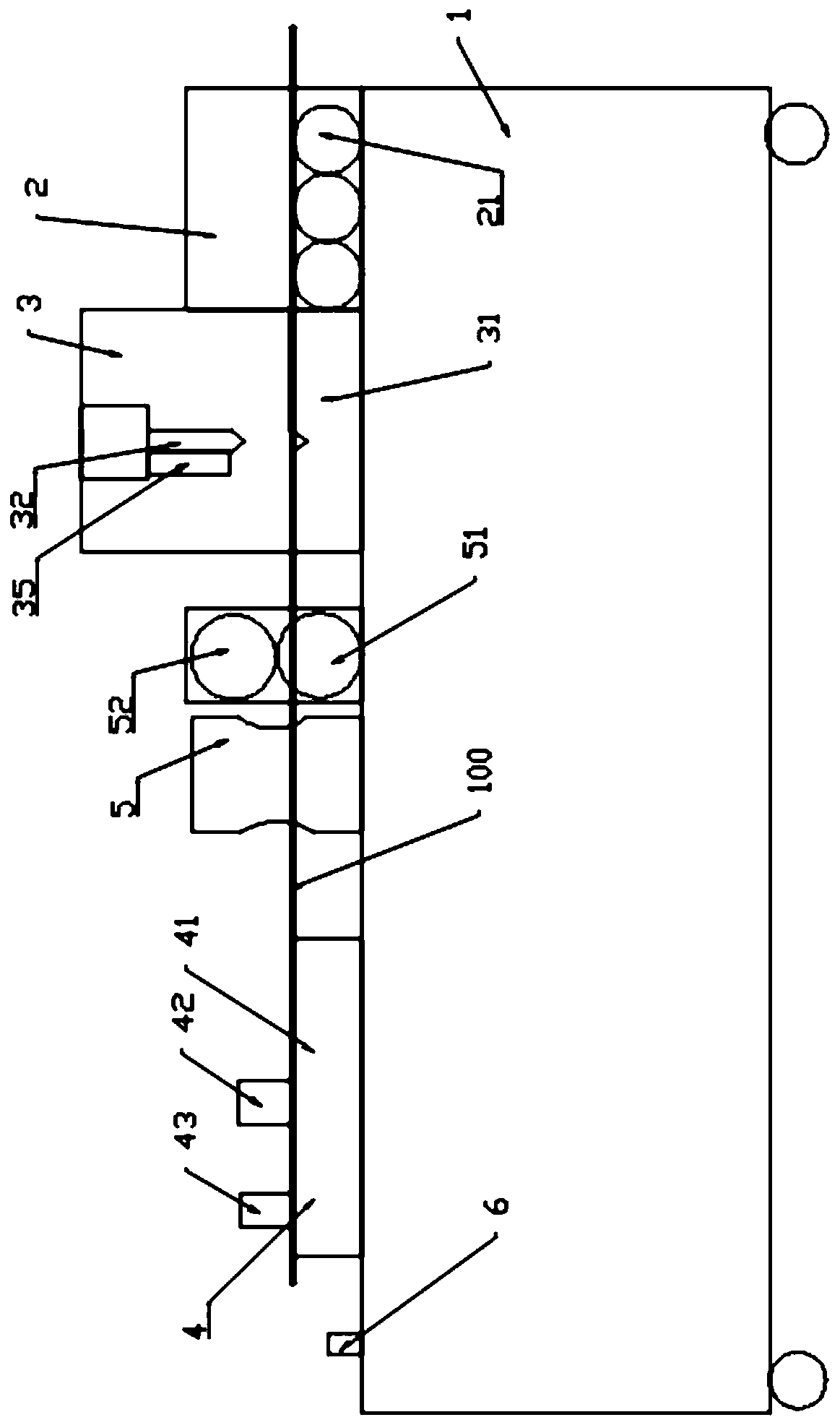
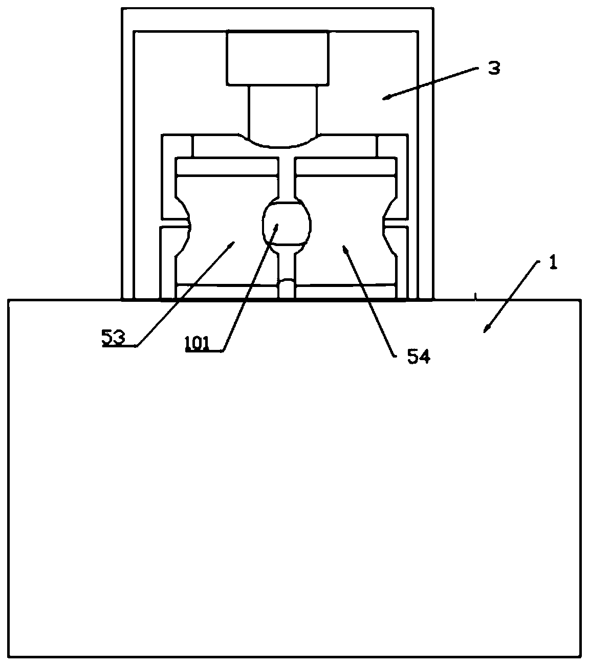
[0024] Example: such as Figure 1-4 As shown, a bendable steel bar cutting device for building construction includes a frame 1 and a conveying mechanism 2 , a cutting mechanism 3 and a bending mechanism 4 arranged on the frame. Wherein, the conveying mechanism includes a steel bar inlet and a steel bar outlet, and a conveying roller assembly is arranged between the steel bar inlet and the steel bar outlet. The conveying roller assembly includes a plurality of rolling shafts 21 arranged side by side in a transverse direction, and the steel bar 100 is transported to the subsequent cutting mechanism and bending mechanism through the rolling of the roller shafts.

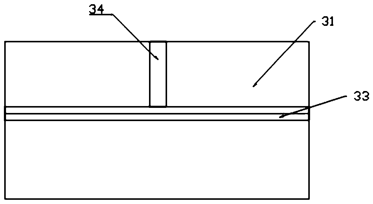
[0025] The cutting mechanism 3 includes a cutting base 31 and a retractable cutting knife 32 located on the top of the cutting base. The cutting base plate is placed horizontally, and a transverse slot 33 is arranged on the cutting base plate, and the cutting tool is located above the cutting base plate and opposite to...


PUM


Abstract

The invention discloses a cutting device capable of bending reinforcing steel bars for building construction. The cutting device comprises a rack, a conveying mechanism, a cutting mechanism, a guide clamping mechanism and a bending mechanism, wherein the conveying mechanism, the cutting mechanism, the guide clamping mechanism and the bending mechanism are arranged on the rack. The conveying mechanism comprises a reinforcing steel bar inlet and a reinforcing steel bar outlet, a conveying roller shaft component is arranged between the reinforcing steel bar inlet and the reinforcing steel bar outlet, and the outlet is opposite to the cutting mechanism. The cutting mechanism comprises a cutting bottom plate and a telescopic cutting tool. An outlet of the cutting mechanism is opposite to the guide clamping mechanism, and an outlet of the guide clamping mechanism is opposite to the bending mechanism. Furthermore, the cutting mechanism comprises the cutting bottom plate and the cutting tool,and a clamping groove for clamping a reinforcing steel bar is formed in the cutting tool. The cutting device achieves integration of cutting and bending of reinforcing steel bars, and can ensure the precision and reliability of cutting and bending.

Description

technical field [0001] The invention relates to an integrated machine for cutting and bending steel bars for house construction. Background technique [0002] A large number of steel bars need to be applied in the process of housing construction, and in order to facilitate loading, unloading and transportation, the steel bars are usually transported to the construction site in a straight state. However, in the construction site, it is often necessary to bend the steel bar to a certain angle or cut it to a certain length for use. In the existing use process, it is usually necessary to use a cutting device to first cut off the steel bar, and then use a steel bar bending machine to bend the steel bar with a certain length. As a result, the process is cumbersome and time-consuming, and the bending accuracy cannot be guaranteed during the cutting and bending process. [0003] In the Chinese patent CN207563634U, a steel bar bending and cutting integrated device is disclosed, and...

Claims


Application Information

Patent Timeline
Patent Type & Authority Applications(China)
IPC IPC(8): B21F11/00B21F1/00B21F23/00
CPCB21F1/00B21F11/00B21F23/00
Inventor 冀小辉
Owner HENAN NO 1 CONSTR ENG GRP
Why Eureka
Try Eureka