
Manufacturing tool and manufacturing method of crane top structural part

A technology for structural parts and a manufacturing method, applied in the field of mechanical processing, can solve the problems of difficult to guarantee the position, high scrap rate of crane structural parts, difficult to meet the requirements of the dimensional accuracy of crane structural parts, etc.

Active Publication Date: 2020-04-10
WUHAN MARINE MACHINERY PLANT
View PDF6 Cites 2 Cited by
  • Summary
  • Abstract
  • Description
  • Claims
  • Application Information

AI Technical Summary

Problems solved by technology

However, there are many structural parts on the top of the crane, and it is difficult to ensure the position between the neutral plate and the two side plates. As a result, the dimensional accuracy of the final crane structural parts cannot meet the requirements, and the scrap rate of the crane structural parts is high.

Method used


Image

  • Manufacturing tool and manufacturing method of crane top structural part
  • Manufacturing tool and manufacturing method of crane top structural part
  • Manufacturing tool and manufacturing method of crane top structural part

Examples


Embodiment Construction

[0040] In order to make the object, technical solution and advantages of the present invention clearer, the embodiments of the present invention will be further described in detail below in conjunction with the accompanying drawings.

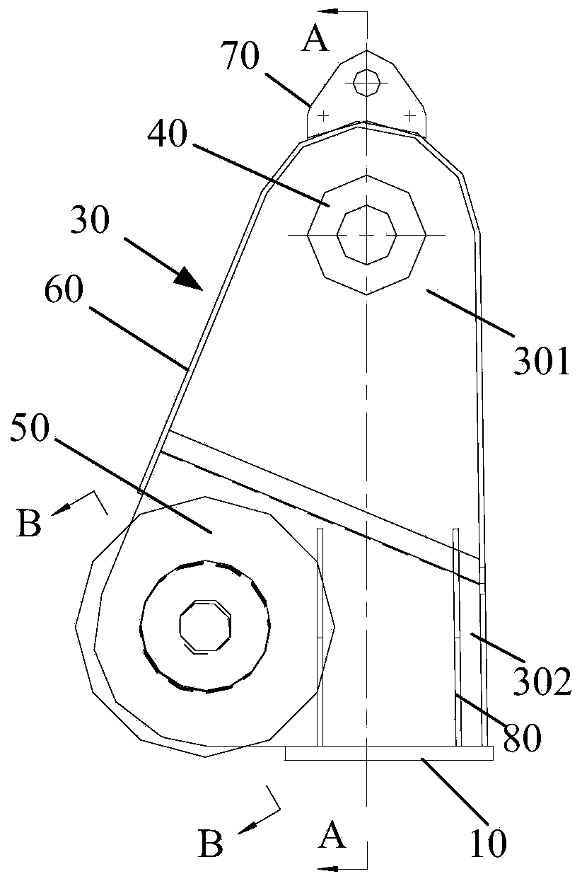
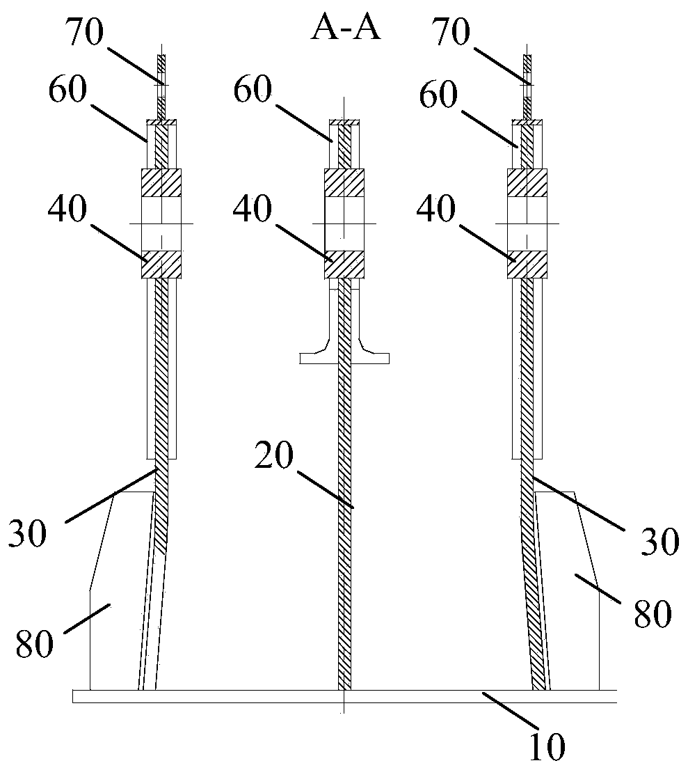
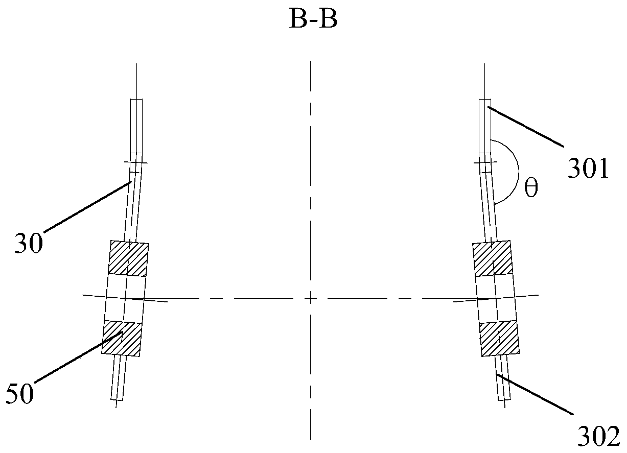
[0041] figure 1 It is a structural schematic diagram of the crane top structure provided by the embodiment of the present invention, figure 2 It is a schematic diagram of the A-A direction of the top structure of the crane provided by the embodiment of the present invention, image 3 It is a schematic diagram of the B-B direction of the top structure of the crane provided by the embodiment of the present invention, combined with figure 1 and figure 2 , the top structure of the crane includes a bottom plate 10, a neutral plate 20, two side plates 30, a pulley flange 40 and a strut flange 50, the neutral plate 20 and the two side plates 30 are all arranged on the bottom plate 10, and the two side plates 30 are symmetrically arranged on both s...


PUM


Abstract

The invention discloses a manufacturing tool and manufacturing method of a crane top structural part, and belongs to the field of machining. Firstly, a middle vertical plate is welded on a bottom plate, a cylindrical bulge of a first positioning shaft is inserted into a pulley flange of the middle vertical plate, a second positioning shaft is inserted into a pulley flange of a side plate, a positioning ring is supported on the pulley flange of the side plate, a positioning plate abuts against the plate surface of one side plate, the second positioning shaft is in threaded connection to the first positioning shaft, and a positioning bolt is rotated to enable one end of the positioning bolt to abut against the pulley flange of the side plate; the position of one side plate relative to the middle vertical plate is fixed by one positioning unit, and the position of the other side plate relative to the middle vertical plate is positioned by another positioning unit, so that the position accuracy of the two side plates relative to the middle vertical plate is ensured; the positions of the two side plates relative to the middle vertical plate are further guaranteed through a supporting unit; and finally, the two side plates and the bottom plate are welded. The size precision of the obtained crane structural part is high, and the rejection rate of the crane structural part can be reduced.

Description

technical field [0001] The invention relates to the field of mechanical processing, in particular to a manufacturing tool for crane top structural parts and a manufacturing method thereof. Background technique [0002] The top structure of the crane is an important force-bearing part of the marine crane. The top structure of the crane includes a bottom plate, a neutral plate, two side plates, a pulley flange and a strut flange. The neutral plate and the two side plates are set on the bottom plate. The two side panels are arranged symmetrically on both sides of the neutral panel, and each side panel is a bent panel with a certain angle. The two side plates and the neutral plate are equipped with a pulley flange correspondingly. The pulley is installed on the pulley flange. The two side plates are provided with corresponding strut flanges. The strut on the jib of the crane is installed on the on the strut flange. [0003] The crane top structure itself needs to have high dim...

Claims


Application Information

Patent Timeline
Patent Type & Authority Applications(China)
IPC IPC(8): B23P15/00
CPCB23P15/00
Inventor 方松戴明飞杨新明
Owner WUHAN MARINE MACHINERY PLANT
Learn More