Alloy precise machining equipment capable of actively verifying product and working method thereof

A precision processing and product technology, applied in the direction of metal processing equipment, metal processing, metal processing machinery parts, etc., can solve the problems of automatic loading and unloading, low degree of automation, futile processing actions, etc., to reduce costs and energy consumption , Reduce labor demand and improve production efficiency

Active Publication Date: 2020-04-10
驰逸自动化科技(苏州)有限公司
View PDF6 Cites 0 Cited by
  • Summary
  • Abstract
  • Description
  • Claims
  • Application Information

AI Technical Summary

Problems solved by technology

[0005] 1. The current processing equipment can only mechanize the processing of workpieces. Even for unqualified products, it will perform futile processing actions, which greatly affects production efficiency and increases production costs.
[0006] 2. The current processing equipment still has the problem of low degree of automation. It can only process automatically, but cannot perform automatic loading and unloading. The production efficiency is poor and the labor demand is high.

Method used


Image

  • Alloy precise machining equipment capable of actively verifying product and working method thereof
  • Alloy precise machining equipment capable of actively verifying product and working method thereof
  • Alloy precise machining equipment capable of actively verifying product and working method thereof

Examples


Embodiment 1

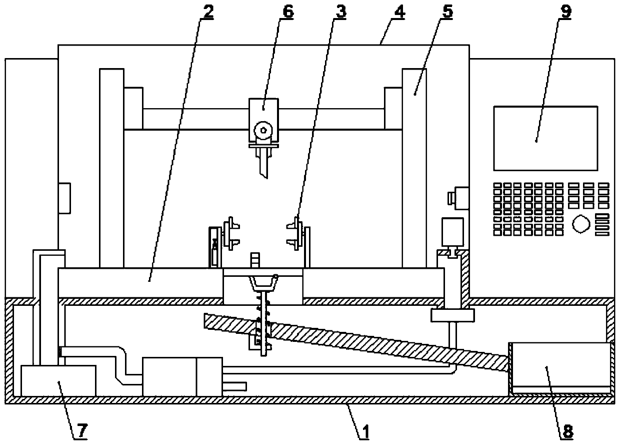
[0043] like Figure 1-9 The alloy precision processing equipment that actively verifies products is shown, including: base 1, working platform 2, fixture 3, protective cabin 4, multi-axis moving mechanism 5, working knife 6, air blowing mechanism 7 and loading and unloading mechanism 8 , the top of the base 1 is provided with a working platform 2, the center of the working platform 2 is provided with a clamp 3, and the outer side of the working platform 2 is provided with a protective cabin 4, and the protective cabin 4 covers the working platform 2. One side of the platform 2 is provided with a multi-axis moving mechanism 5, the rudder shaft moving mechanism 5 penetrates into the base 1, the rudder shaft moving mechanism 5 is arranged in the protective cabin 4, and the rudder shaft moving mechanism 5 is provided with Working knife 6, described working knife 6 is arranged on the top of working platform 2, and described working platform 2 side is provided with blowing mechanism...

Embodiment 2

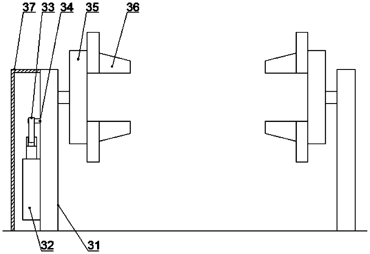
[0055] like Figure 1-3 The alloy precision processing equipment that actively verifies products is shown, including: base 1, working platform 2, fixture 3, protective cabin 4, multi-axis moving mechanism 5, working knife 6, air blowing mechanism 7 and loading and unloading mechanism 8 , the top of the base 1 is provided with a working platform 2, the center of the working platform 2 is provided with a clamp 3, and the outer side of the working platform 2 is provided with a protective cabin 4, and the protective cabin 4 covers the working platform 2. One side of the platform 2 is provided with a multi-axis moving mechanism 5, the rudder shaft moving mechanism 5 penetrates into the base 1, the rudder shaft moving mechanism 5 is arranged in the protective cabin 4, and the rudder shaft moving mechanism 5 is provided with Working knife 6, described working knife 6 is arranged on the top of working platform 2, and described working platform 2 side is provided with blowing mechanism...

Embodiment 3

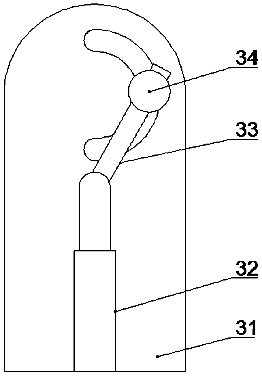
[0059] like figure 1 , 4 An alloy precision machining equipment for actively verifying products shown in and 5, including: a base 1, a working platform 2, a fixture 3, a protective cabin 4, a multi-axis moving mechanism 5, a working knife 6, an air blowing mechanism 7 and a loading and unloading mechanism. Mechanism 8, the top of the base 1 is provided with a working platform 2, the center of the working platform 2 is provided with a clamp 3, and the outer side of the working platform 2 is provided with a protective cabin 4, and the protective cabin 4 covers the working platform 2. One side of the working platform 2 is provided with a multi-axis moving mechanism 5, the rudder shaft moving mechanism 5 penetrates into the base 1, the rudder shaft moving mechanism 5 is arranged in the protective cabin 4, and the rudder shaft moving mechanism 5 A working knife 6 is provided, and the working knife 6 is arranged on the top of the working platform 2. A blowing mechanism 7 is provide...


PUM


Abstract

The invention discloses alloy precise machining equipment capable of actively verifying a product. The equipment comprises a base, a working platform, a clamp, a protection cabin, a multi-axis movingmechanism, a working knife, an air blowing mechanism and a feeding and discharging mechanism, wherein the working platform is arranged at the top of the base, the clamp is arranged in the center of the working platform, the protection cabin is arranged on an outer side of the working platform, the multi-axis moving mechanism is arranged on one side of the working platform, the working knife is arranged on the multi-axis shaft moving mechanism, the air blowing mechanism and the feeding and discharging mechanism are arranged on one side of the working platform. The device further comprises a detection mechanism. The invention further discloses a working method of the alloy precision machining equipment for actively verifying the product. The equipment is advantaged in that on one hand, the detection part is additionally arranged, a machined workpiece is monitored in real time through photoelectric separation, unqualified products are abandoned in time, production efficiency is improved,and cost and energy consumption are reduced; and on the other hand, an automatic feeding and discharging function is provided, functionality of the equipment is enhanced, and the manual requirement isreduced.

Description

technical field [0001] The invention belongs to the field of gold processing equipment and technology, in particular to an alloy precision processing equipment for actively verifying products and a working method thereof. Background technique [0002] With the development of modern industry and science and technology, the current gold processing equipment is constantly developing in the direction of automation and precision. Due to the outstanding performance of metal processing equipment in processing techniques such as turning, milling, grinding, and cutting, its use in the market is becoming wider and wider. Under the trend of enterprise transformation, the cost of labor is getting higher and higher. In this environment, the demand for gold processing equipment in manufacturing enterprises is increasing. [0003] Due to the increase in labor costs and processing scale, companies now begin to invest a lot of manpower and material resources in the research and development ...

Claims


Application Information

Patent Timeline
Patent Type & Authority Applications(China)
IPC IPC(8): B23Q7/00B23Q17/24B23Q17/20B23Q11/00
CPCB23Q7/00B23Q11/00B23Q11/005B23Q17/20B23Q17/24
Inventor 周逸
Owner 驰逸自动化科技(苏州)有限公司
Why Eureka
Try Eureka