Lifting device with self-adaptive uniform loading function

A lifting device, self-adaptive technology, applied in the direction of lifting device, lifting frame, etc., can solve the problems of increased load and energy consumption, inapplicability, large space occupied, etc., to reduce eccentric load and stress concentration, improve allowable Effects of load, load reduction and energy consumption

Pending Publication Date: 2020-04-10
ZHENGZHOU YUTONG HEAVY IND
View PDF9 Cites 0 Cited by
  • Summary
  • Abstract
  • Description
  • Claims
  • Application Information

AI Technical Summary

Problems solved by technology

If there are processing and installation errors, it will cause the screw and the nut to deflect each other, and cannot automatically adapt or adjust the adverse effects caused by the error, so it is easy to cause unbalanced load or even motion interference, which not only reduces the lift. Bearing capacity and service life, but also reduce efficiency, increase additional additional load and energy consumption
[0004] The existing methods to solve or alleviate the eccentric load of the screw and the nut mainly include: improving the machining and installation accuracy, modifying the thread profile of the nut or the screw, and reducing the eccentric load from a microscopic point of view. Applications that exceed a large range of error are not applicable
In particular, for the occasions that need to achieve rotary motion or angular swing, although the prior art can use a screw-moving elevator to achieve it, the screw-moving elevator requires a large space, and at the same time due to the specific space When the size is limited and a nut-moving elevator must be used, the existing common nut-moving elevator is difficult to solve the problem of movement interference between the lead screw and the nut in principle.

Method used


Image

  • Lifting device with self-adaptive uniform loading function
  • Lifting device with self-adaptive uniform loading function
  • Lifting device with self-adaptive uniform loading function

Examples


Embodiment Construction

[0020] The technical solutions of the present invention will be described in detail below in conjunction with the accompanying drawings and specific embodiments. It should be noted that the "connection" mentioned in this application and the words used to express "connection", such as "connected", "connected", etc., include not only the direct connection between a certain component and another component, but also the direct connection of a certain component. One part is connected to another part through other parts.

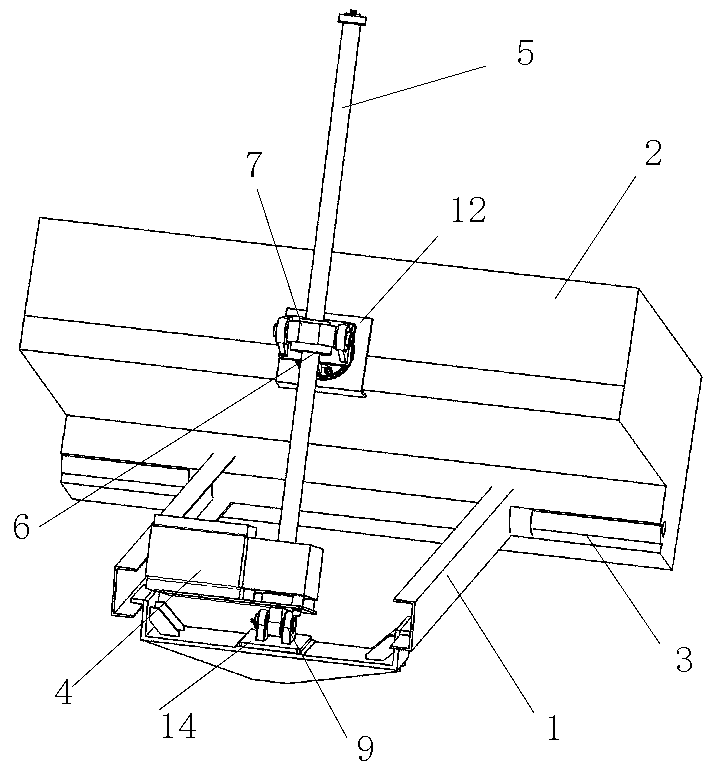
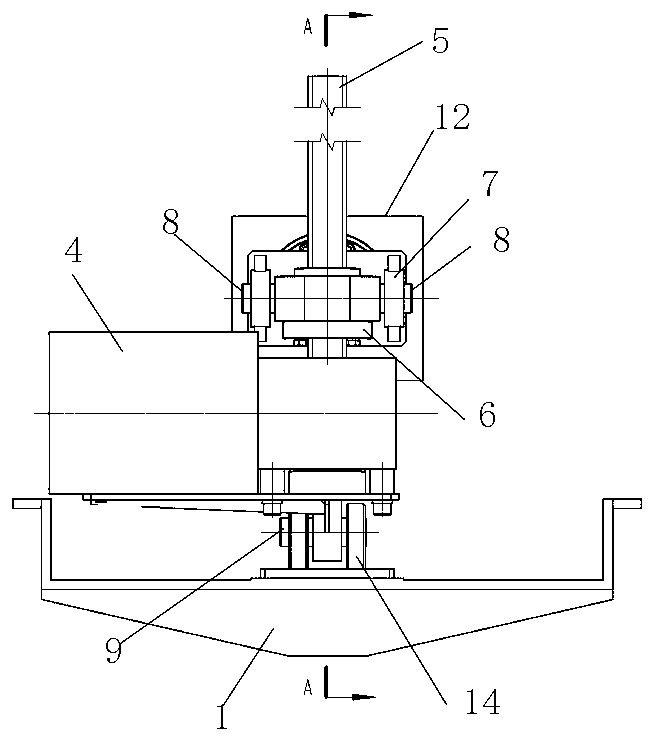
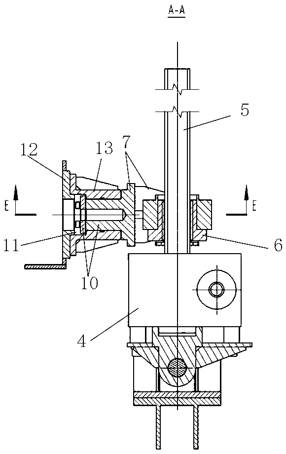
[0021] like figure 1 - As shown in 5, the lifting device with self-adaptive load balancing function includes a bottom plate 1 and a box body 2 connected with the bottom plate 1 around the rotary shaft 3 in rotation, a hinged screw nut mechanism between the bottom plate 1 and the box body 2, and a screw nut mechanism. The rod and nut mechanism includes a driving mechanism 4 , a screw 5 driven by the driving mechanism 4 and a nut 6 arranged on the leading screw 5 ,...


PUM


Abstract

The invention provides a lifting device with a self-adaptive uniform loading function. The lifting device comprises a bottom plate and a box body rotationally connected with the bottom plate. A lead screw and nut mechanism is hinged between the bottom plate and the box body. The lead screw and nut mechanism comprises a drive mechanism, a lead screw driven by the drive mechanism to rotate and a nutarranged on the lead screw. The drive mechanism is hinged to the bottom plate, and the nut is hinged to the box body. A self-adaptive mechanism capable of enabling the nut to rotate around two vertical axes is arranged between the nut and the box body. Or a self-adaptive mechanism capable of enabling the drive mechanism to rotate around the two vertical axes is arranged between the drive mechanism and the bottom plate. The lifting device has the beneficial effects that it can be guaranteed that cooperation of lead screw and nut transmission pairs is in an ideal contact state, then unbalance loading and stress concentration are greatly reduced, allowable loads of the lead screw and nut transmission pairs are increased, the bearing capacity of the lead screw and nut transmission pairs is improved, the service life of the lead screw and nut transmission pairs is prolonged, and additional loads and energy consumption are reduced.

Description

technical field [0001] The invention belongs to the field of mechanical transmission, and in particular relates to a lifting device with an adaptive load equalizing function. Background technique [0002] In the field of mechanical transmission, especially in the field of elevators, screw transmission pairs are often used as the main mechanism for realizing translation and rotation of objects. According to the movement mode, the elevator can be divided into screw movement type and nut movement type; according to the transmission principle, it can be divided into ordinary gear screw type, roller screw screw type and roller screw screw type; according to the driving form, it can be divided into cylindrical gear transmission drive, bevel gear drive, worm gear drive and direct drive. [0003] At present, because the elevator uses bearings to support the moving parts, the connection and coordination rigidity of the box, screw and nut of the elevator is relatively high, and there...

Claims


Application Information

Patent Timeline
Patent Type & Authority Applications(China)
IPC IPC(8): B66F7/14B66F7/28
CPCB66F7/14B66F7/28
Inventor 丁爽杨仲磊郭海乐张艳云张增姜卫生任振宇
Owner ZHENGZHOU YUTONG HEAVY IND
Why Eureka
Try Eureka