Welding method and weld joint

A welding method, technology of the welding department, applied in the direction of welding/welding/cutting articles, welding equipment, welding medium, etc.

Inactive Publication Date: 2014-07-09
OSAKA UNIV
View PDF12 Cites 7 Cited by
  • Summary
  • Abstract
  • Description
  • Claims
  • Application Information

AI Technical Summary

Problems solved by technology

However, even with this technology, the improvement in the fatigue life of the welded part is at most about 1.5 to 2 times that of the conventional one.

Method used


Image

  • Welding method and weld joint
  • Welding method and weld joint
  • Welding method and weld joint

Examples


Embodiment Construction

[0095] Hereinafter, the present invention will be described based on the embodiments. In addition, this invention is not limited to the following embodiment. Various modifications can be added to the following embodiments within the same and equivalent scope as the present invention.

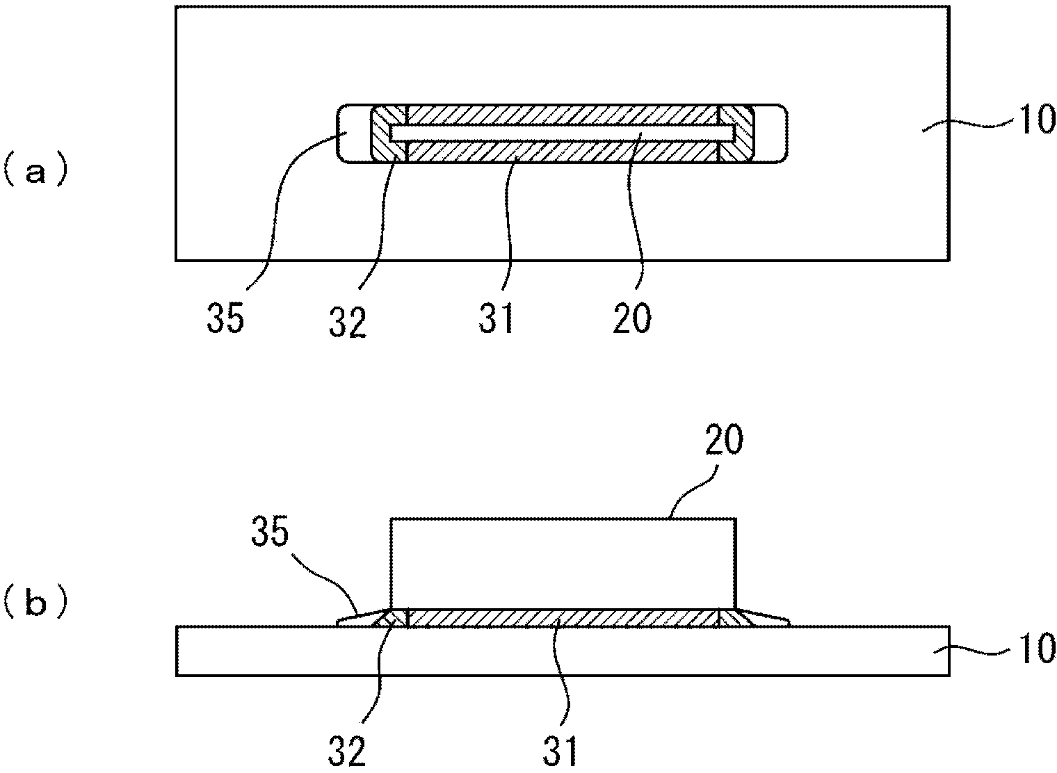
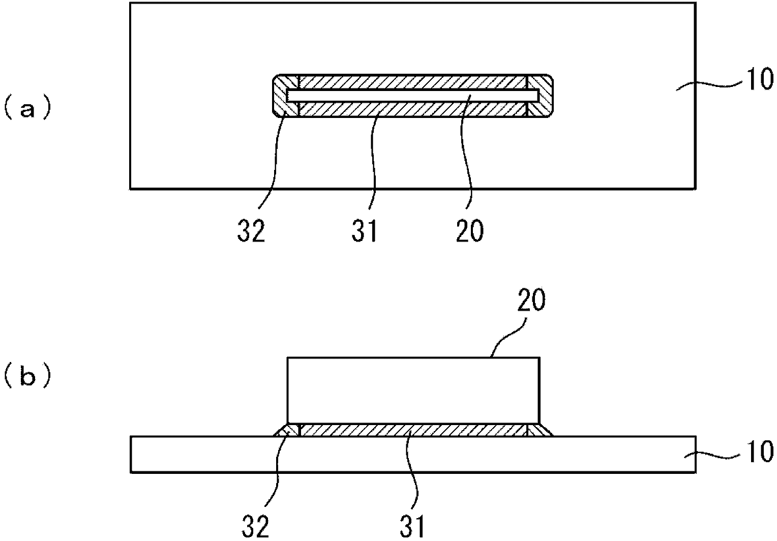
[0096] First, an outline of a welded joint according to the present invention and an outline of a conventional welded joint will be described using the drawings. figure 1 Table shows the welded joint made by the welding method of the present invention, in addition, figure 2 The table in the table shows welded joints produced by conventional welding methods. figure 1 , 2 In each drawing, (a) is a plan view, and (b) is a side view.

[0097] figure 2 In the conventional welded joint shown in , conventional fillet welding is used to weld a flat plate 10 as a base material to a gusset plate 20 to form a welded portion 31 and a fillet welded portion 32 on the lower side of the gusset plate 20...


PUM

PropertyMeasurementUnit
lengthaaaaaaaaaa
lengthaaaaaaaaaa
lengthaaaaaaaaaa

Abstract

Provided are a welding method and a weld joint with which the fatigue strength of the box-welded joint of a gusset plate and a high-tensile steel can be dramatically improved. A welding method whereby a gusset plate is welded to high-tensile steel by means of box-welding, with a bead having a length of 17mm or greater being formed at the ends of the gusset plate in the lengthwise direction using a welding material for which the martensite transformation starting temperature of the welding metal is 350 DEG C or less. In addition, a weld joint formed by welding a gusset plate to high-tensile steel using the aforementioned method is disclosed. In addition, a method for repairing or reinforcing, by means of welding, a box-welded part comprising a gusset in an existing steel structure and a parent material, wherein a bead is formed such that the length of the bead part from the ends of a gusset plate of the box-welded part is 17 mm or greater in the lengthwise direction at the ends of the gusset plate, using a welding material for which the martensite transformation starting temperature of the welding metal is 350 DEG C or less.

Description

technical field [0001] The present invention relates to a welding method for fillet welding a gusset plate to high-strength steel in a welded structure using high-strength steel. Background technique [0002] In order to increase the size of welded structures such as ships, marine structures, and bridges, and to reduce the weight and safety associated with them, in recent years, high-strength steels whose tensile strength has been increased from 500 MPa to 1000 MPa have gradually begun to be used. [0003] The fatigue strength represented by the fatigue life and fatigue limit of the base material also increases in proportion to the high strength, but the fatigue strength of the welded part does not increase as long as the conventional welding technology is used. [0004] Among the welded parts, there are various types of welded parts such as butt welded parts, fillet welded parts and corner welded parts, but among them, the corner welded part when the gusset plate is welded ...

Claims


Application Information

Patent Timeline
Patent Type & Authority Applications(China)
IPC IPC(8): B23K31/00B23K9/02B23K9/23B23K35/30
CPCB23K9/0043B23K9/0256B23K9/23B23K31/00B23K35/30B23K35/3053B23K2103/04B23K2101/18B23K31/02F16B5/08
Inventor 志贺千晃平冈和雄
Owner OSAKA UNIV
Why Eureka
Try Eureka