Fibrous-composite-wound pressure container with thin-walled metal lining and manufacturing process thereof

A fiber composite material and pressure vessel technology, applied in the field of pressure vessels, can solve the problems of pressure vessel leakage, interface debonding failure, pressure vessel weight increase, etc., to increase the allowable load, fully seal, and avoid local stress. concentrated effect

Inactive Publication Date: 2016-03-30
DALIAN UNIV OF TECH
View PDF5 Cites 17 Cited by
  • Summary
  • Abstract
  • Description
  • Claims
  • Application Information

AI Technical Summary

Problems solved by technology

When unloading, the composite material layer undergoes complete elastic recovery, and the metal lining can only undergo elastic partial recovery, and a large part of the plastic deformation cannot be recovered, and residual compressive stress appears in the metal lining, so that during repeated loading and unloading cycles, the metal lining Buckling under external pressure causes debonding failure at the interface between the metal lining and the fiber composite winding layer, resulting in leakage of the pressure vessel, which limits the allowable load of the pressure vessel and reduces the fatigue resistance and blast resistance of the pressure vessel
In order to enable the metal lining to experience repeated cycles of tension and compression stress without failure, a thicker metal lining is often required, resulting in a large increase in the weight of the pressure vessel

Method used


Image

  • Fibrous-composite-wound pressure container with thin-walled metal lining and manufacturing process thereof
  • Fibrous-composite-wound pressure container with thin-walled metal lining and manufacturing process thereof
  • Fibrous-composite-wound pressure container with thin-walled metal lining and manufacturing process thereof

Examples


Embodiment Construction

[0031] In order to make the purpose, technical solutions and advantages of the embodiments of the present invention clearer, the technical solutions in the embodiments of the present invention will be clearly and completely described below in conjunction with the drawings in the embodiments of the present invention. Obviously, the described embodiments It is a part of embodiments of the present invention, but not all embodiments. Based on the embodiments of the present invention, all other embodiments obtained by persons of ordinary skill in the art without making creative efforts belong to the protection scope of the present invention.

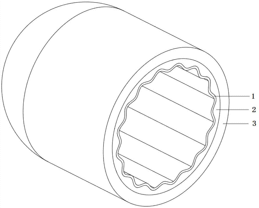
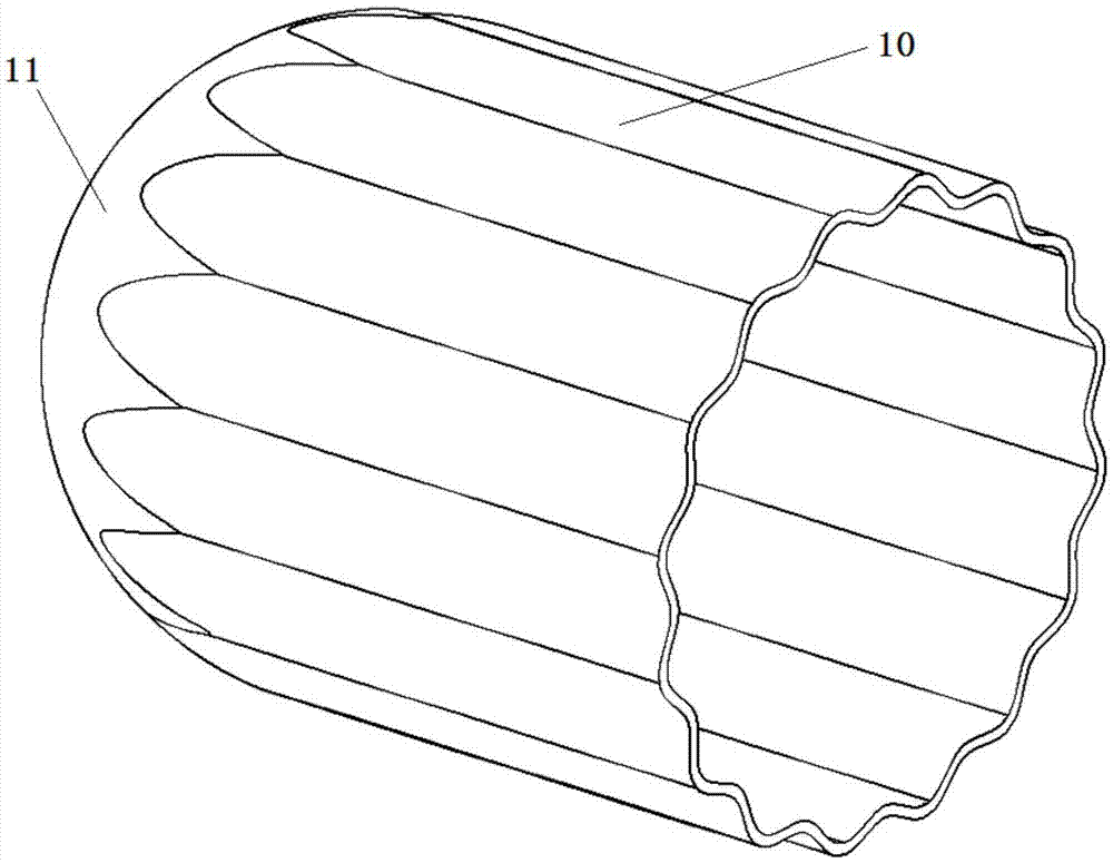
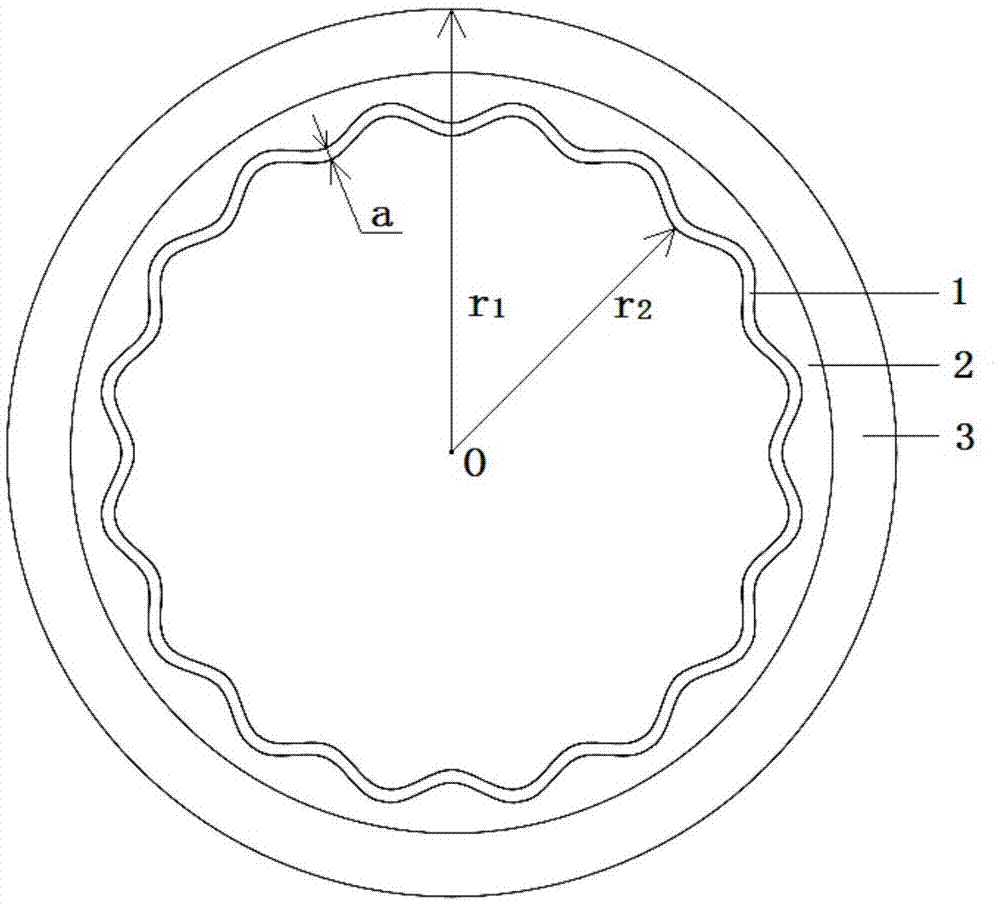
[0032] Such as Figure 1-Figure 3 The thin-walled metal-lined fiber composite wound pressure vessel shown in the first embodiment includes a liner 1 , an elastic material filling layer 2 , a fiber composite wound layer 3 and a medium inlet and outlet (not shown).

[0033] The inner liner 1 includes a thin-walled metal tubular structure inner...


PUM


Abstract

The invention discloses a fibrous-composite-wound pressure container with a thin-walled metal lining and a manufacturing process thereof. The pressure container is characterized in that a lining barrel body section is of a thin-walled metal tube structure, and the wall face of the lining barrel body section is corrugated; the pressure container further comprises an elastic material filling layer wrapped outside the lining barrel body section; a fibrous composite winding layer is wrapped outside the elastic material filling layer and a lining end closure section. The manufacturing process of the pressure container includes the steps of S1, manufacturing the lining through a thin-walled metal material, S2, wrapping elastic materials outside the lining barrel body section and S3, winding fibrous composites varnished in resin on the outer surface of the elastic material filling layer in a layered mode and carrying out curing molding. According to the pressure container and the manufacturing process thereof, the lining, the fibrous composite winding layer and the adjacent layers are not prone to debonding or failures.

Description

technical field [0001] The invention relates to the field of pressure vessels, in particular to a thin-walled metal-lined fiber composite wound pressure vessel and a manufacturing process thereof. Background technique [0002] The metal-lined fiber composite wound pressure vessel consists of a double-layer structure, the inner layer is the inner liner, and its material can be aluminum alloy, stainless steel, pure titanium, titanium alloy and Cornel alloy, etc.; the outer layer is the fiber composite wound layer ( That is, the shell), which is combined with the inner liner by winding a certain number of layers of resin-impregnated fiber composite material on the outer surface of the inner liner, and curing and molding. The barrel section of the pressure vessel is cylindrical, with hemispherical or ellipsoidal heads at both ends. As a pressure fluid storage device, the fiber composite winding layer is the main bearing structure of the internal pressure load, and the inner lin...

Claims


Application Information

Patent Timeline
IPC IPC(8): F17C1/06F17C1/10
CPCF17C1/06F17C1/10F17C2201/0109F17C2201/0138F17C2203/0663
Inventor 王博邹华民任明法黄诚张希周才华丛杰常鑫曹广龙
Owner DALIAN UNIV OF TECH
Why Eureka
Try Eureka