
Intermittent oil recovery control method

A control method and intermittent period technology, applied in the direction of production fluid, earthwork drilling, wellbore/well components, etc., can solve problems such as low production, oil pump emptying or insufficient fullness, and shortened service life of oil production equipment

Inactive Publication Date: 2020-04-10
XI'AN PETROLEUM UNIVERSITY
View PDF5 Cites 0 Cited by
  • Summary
  • Abstract
  • Description
  • Claims
  • Application Information

AI Technical Summary

Problems solved by technology

[0002] The key technical problems in the development of conventional oilfields in the middle and later stages are: insufficient pressure in oil wells, intermittent oil production, serious shortage of liquid supply, inability to continuously produce oil in oil wells, and ultra-low production, resulting in severe air pumping or insufficient fullness of oil pumps to varying degrees This not only causes ineffective wear and tear of pumps, rods, and pumps, reduces the service life of oil production equipment, increases maintenance costs, but also greatly reduces the operating efficiency of pumping units, resulting in a huge waste of electric energy
In the current continuous fixed oil production mode, the phenomenon of dry pumping is very serious, resulting in a huge waste of electric energy and rapid loss of equipment. On average, each oil well is repaired more than once a year, consuming a lot of manpower and equipment resources, resulting in a huge production cost of the oil well. improve
At present, the oil field has a strong demand for advanced intermittent oil recovery technology, and the application of the existing intermittent oil recovery technology cannot obtain very satisfactory results, especially the method that requires additional secondary measuring instruments, which will increase the cost of oil recovery

Method used


Image

  • Intermittent oil recovery control method
  • Intermittent oil recovery control method
  • Intermittent oil recovery control method

Examples


Embodiment Construction

[0021] The present invention is described in detail below in conjunction with accompanying drawing.

[0022] A control method for intermittent oil recovery, comprising the following steps:

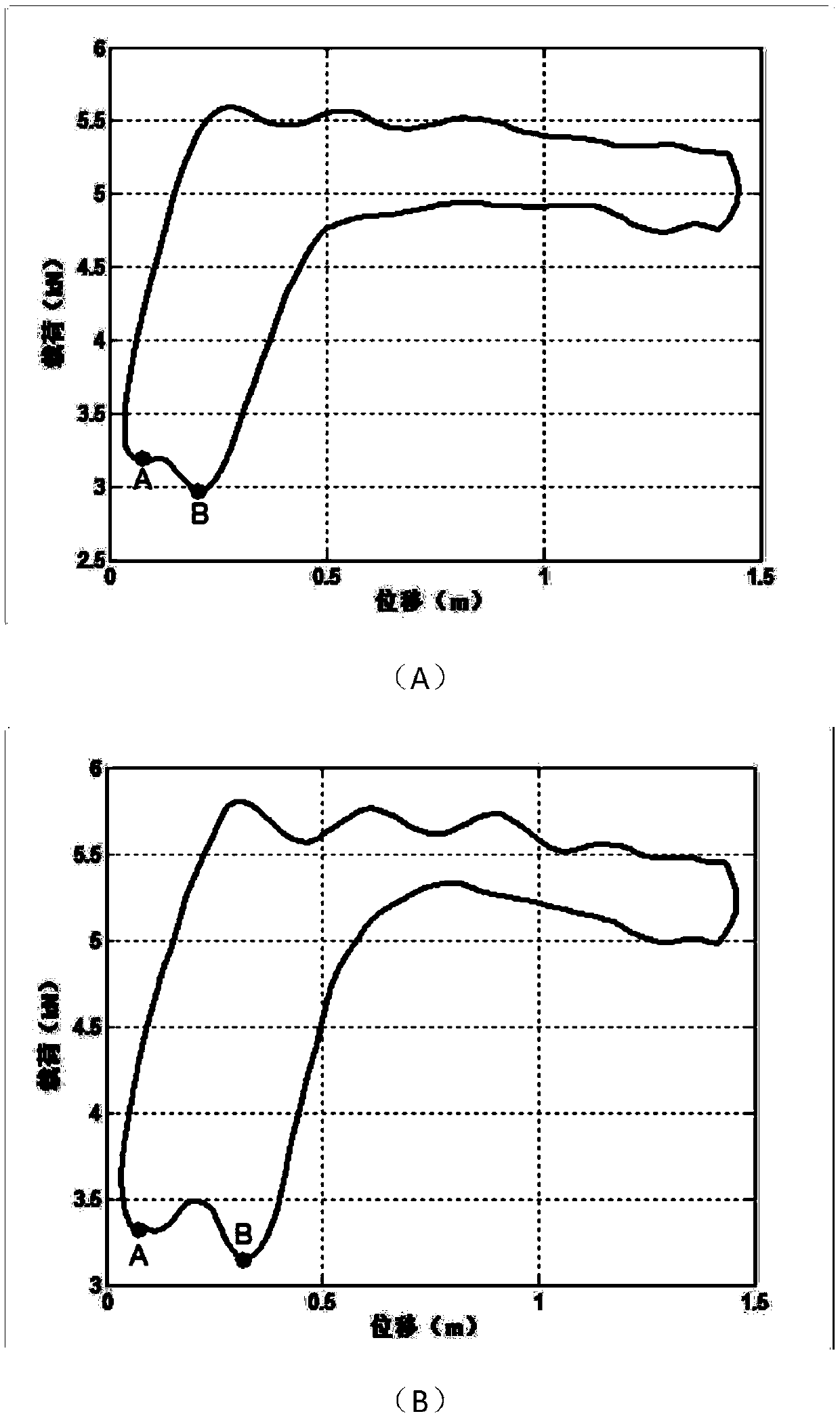
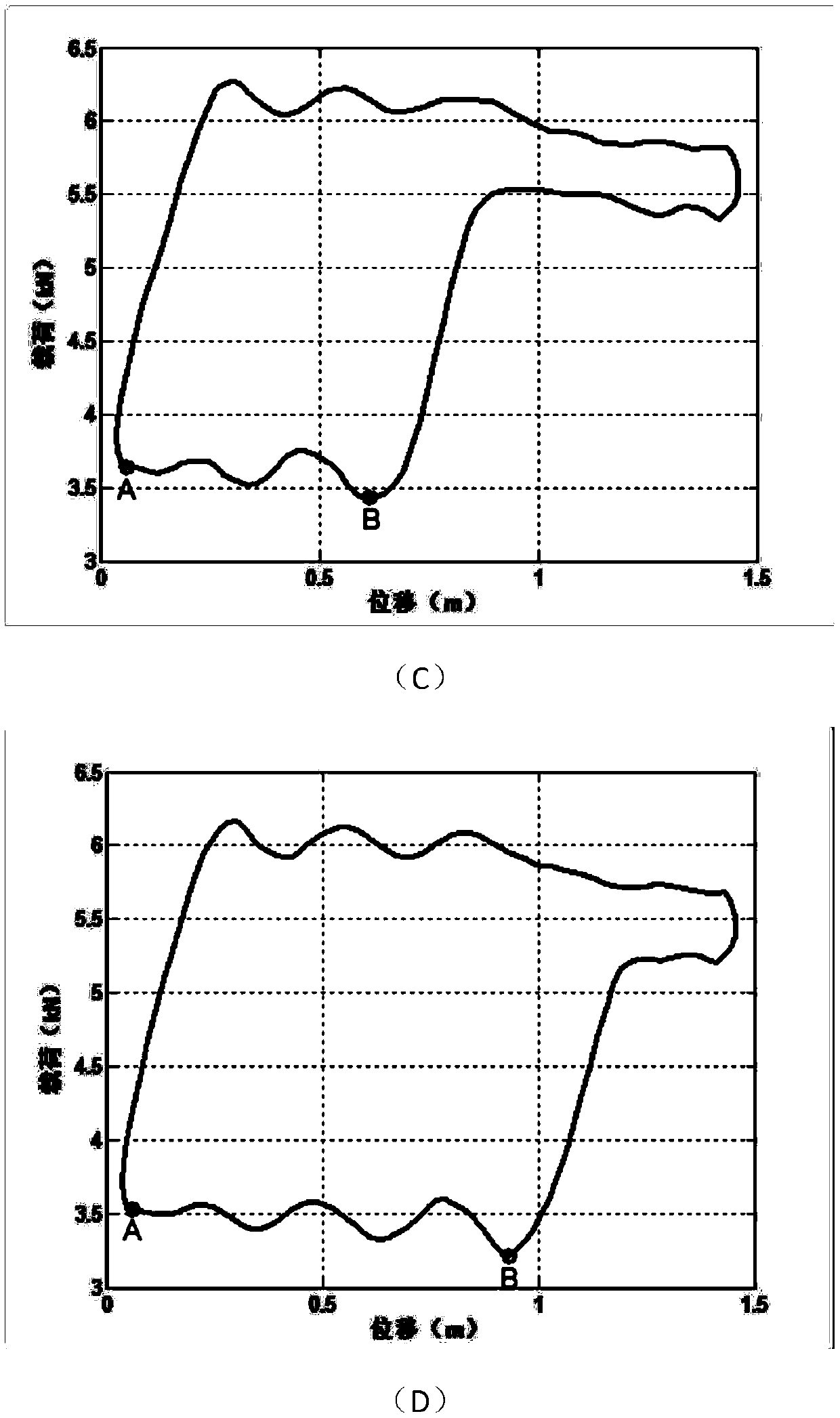
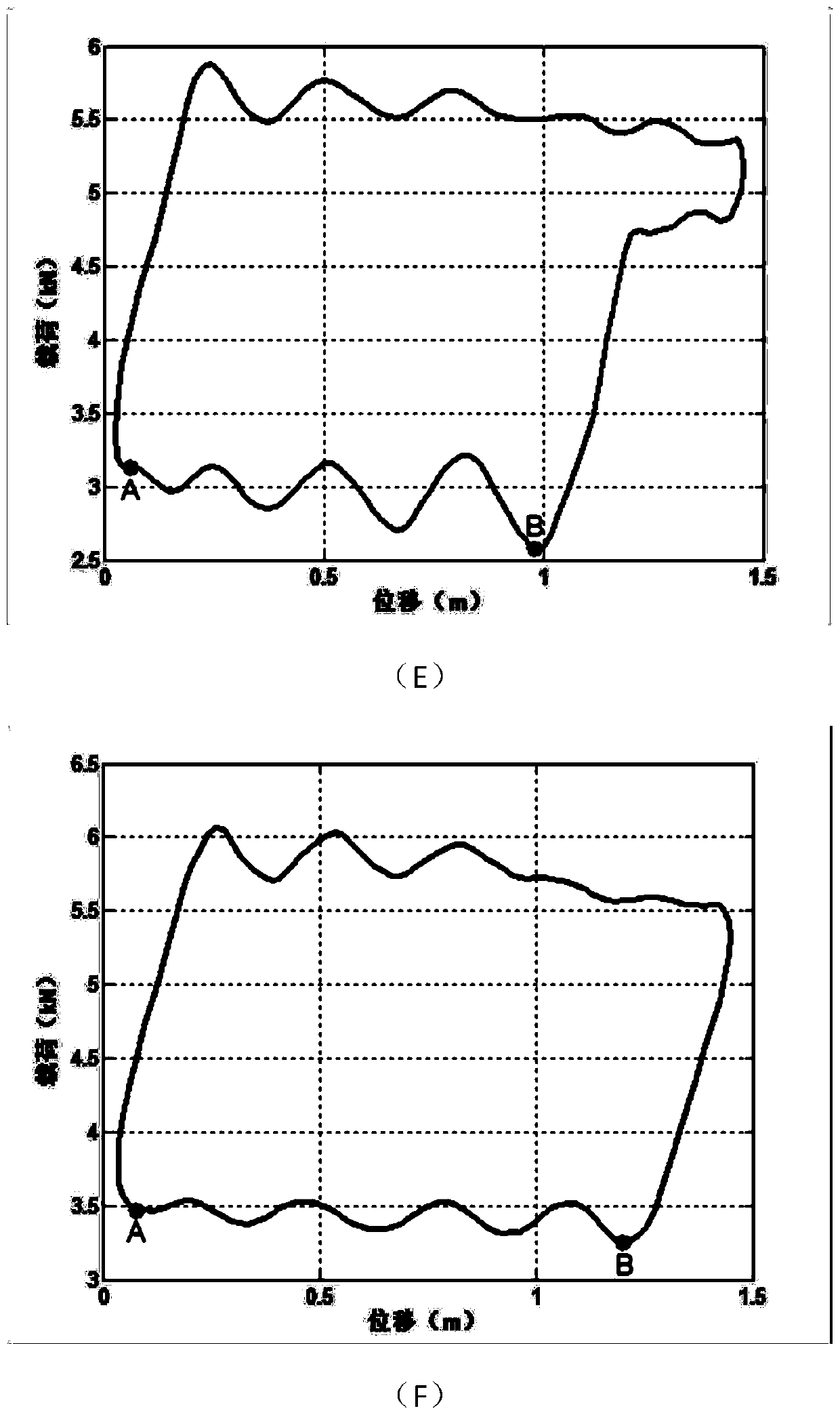
[0023] Step 1: Collect the dynamometer diagram. When the effective stroke of the dynamometer diagram is less than 10% of the plunger stroke, stop and resume, and the shutdown resumes as an intermittent period. During the intermittent period, start to collect the oil well dynamometer diagram every 0.5 hours, 1 hour or 2 hours And record the collection time, and then shut down to get the change law of the effective stroke of the dynamometer diagram in the intermittent period over time, such as figure 1 Shown: During the intermittent period, stop and recover, start up every 0.5 hours to collect the oil well dynamometer diagram, and then shut down, to obtain the change law of the effective travel of the dynamometer diagram during the intermittent period with time.

[0024] Step 2: When the ef...


PUM


Abstract

The invention discloses an intermittent oil recovery control method. The method comprises the following steps that step 1, an indicator diagram is collected, when the effective stroke of the indicatordiagram is less than 10% of the plunger stroke, shutdown for recover is conducted and in an intermittent period, collecting of the indicator diagram of an oil well and recording of the collection time are conducted by adopting starting at intervals in the intermittent period, then shutdown is conducted, and the change rule of the effective stroke of the indicator diagram along with time in the intermittent period is obtained; and step 2, when the effective stroke of the indicator diagram is higher than 90% of the plunger stroke, starting for oil recovery is conducted and in an intermittent pumping period, collecting of the indicator diagram of the oil well and recording of the collection time are conducted at intervals, the change rule of the effective stroke of the effective stroke of the indicator diagram along with time in the intermittent pumping period is obtained, and when the effective stroke of the indicator diagram is less than 10% of the plunger stroke, shutdown for recoveris conducted according to the step 1. By means of the intermittent oil recovery control method, according to the effective stroke length of the indicator diagram in the intermittent pumping period andintermittent period, intermittent oil recovery control can be achieved, in this way, dry pumping of an oil pumping unit can be prevented, and the advantages of improving the oil recovery efficiency is achieved.

Description

technical field [0001] The invention relates to the technical field of oil recovery, in particular to a control method for intermittent oil recovery. Background technique [0002] The key technical problems in the development of conventional oilfields in the middle and later stages are: insufficient pressure in oil wells, intermittent oil production, serious shortage of liquid supply, inability to continuously produce oil in oil wells, and ultra-low production, resulting in severe air pumping or insufficient fullness of oil pumps to varying degrees This not only causes ineffective wear of pumps, rods, and pumps, reduces the service life of oil extraction equipment, increases maintenance costs, but also greatly reduces the operating efficiency of pumping units, resulting in a huge waste of electric energy. The output of a single well is very low. Excluding the normal operation cost of the oil well, the economic benefits of oil well production are already very low, and some ar...

Claims


Application Information

Patent Timeline
IPC IPC(8): E21B43/00E21B47/008
CPCE21B43/00
Inventor 宋红任涛曾威
Owner XI'AN PETROLEUM UNIVERSITY
Learn More