Pumping unit capable of achieving intermittent pumping through non-full-cycle motion of crank without shutdown

A non-circumferential, pumping unit technology, used in production fluids, wellbore/well components, earthmoving, etc., to solve problems such as lack of flow or agitation, inability to adjust the pumping unit stroke in a large range, wellhead freezing and blocking, etc. , to achieve the effect of saving equipment costs, avoiding dry pumping, and reducing oil pumping speed

Pending Publication Date: 2022-01-07
于婷婷
View PDF17 Cites 0 Cited by
  • Summary
  • Abstract
  • Description
  • Claims
  • Application Information

AI Technical Summary

Problems solved by technology

[0003] In the prior art, since the stroke of the pumping unit cannot be adjusted in a wide range, the downhole oil pump can only be stopped by shutting down the pumping unit, but the complete shutdown of the pumping unit will make the liquid in the tubing near the wellhead completely static state, lack of flow or agitation, so it is easy to cause wellhead freezing in winter in the northern alpine region

Method used


Image

  • Pumping unit capable of achieving intermittent pumping through non-full-cycle motion of crank without shutdown
  • Pumping unit capable of achieving intermittent pumping through non-full-cycle motion of crank without shutdown
  • Pumping unit capable of achieving intermittent pumping through non-full-cycle motion of crank without shutdown

Examples


Embodiment 1

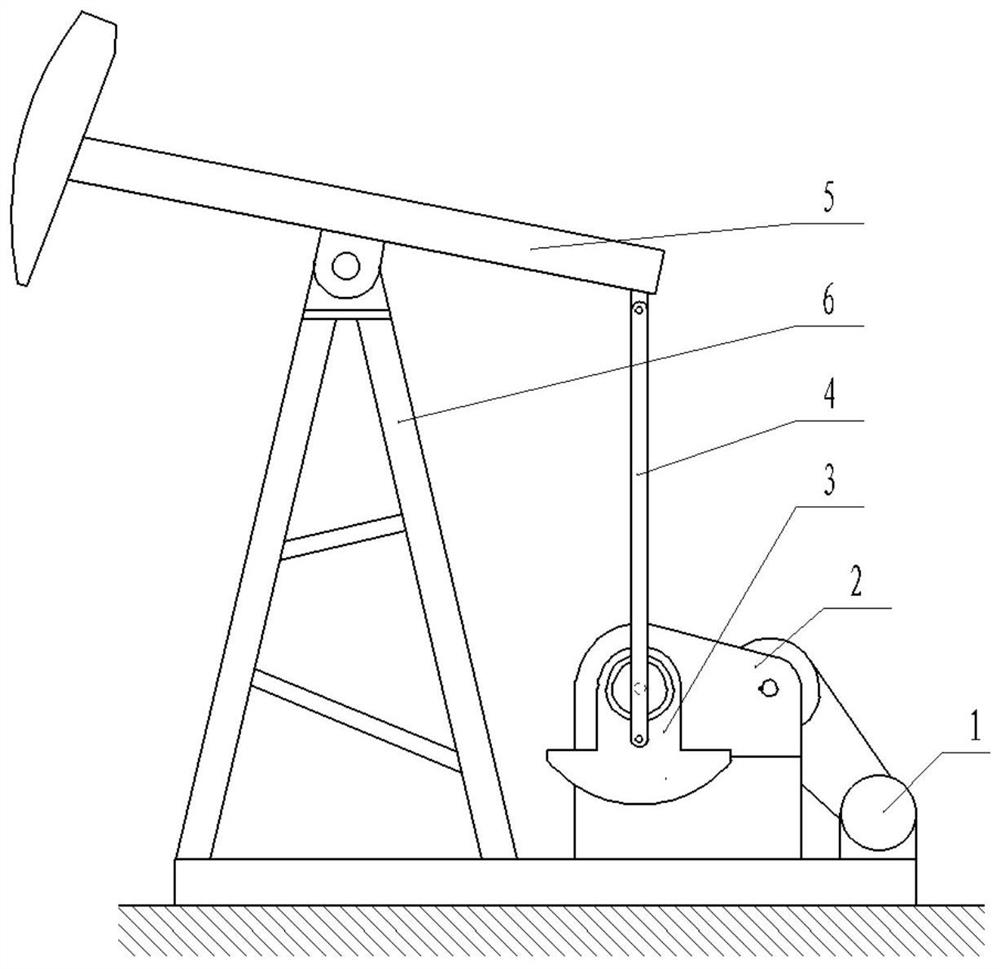
[0034] Such as figure 1 As shown, the present embodiment includes a motor 1, a reducer 2, a crank assembly 3, a connecting rod 4, a beam 5 and a bracket 6, the motor 1 is connected with the input shaft of the reducer 2 through a belt transmission mechanism, and the crank assembly 3 The end is installed on the output shaft 16 of the reducer 2 and rotates under the drive of the reducer 2. The middle part of the beam 5 is hinged on the top of the bracket 6. The upper and lower ends of the connecting rod 4 are respectively hinged on the tail of the beam 5 and the On the crank assembly 3. When working, the power provided by the motor 1 is transmitted to the reducer 2, and then converted into the rotary motion of the crank assembly 3, and the rotary motion of the crank assembly 3 is converted into the reciprocating swing of the beam 5 through the connecting rod 4. The above structure is a conventional structure in the prior art, and will not be repeated here.

[0035] The innovati...

Embodiment 2

[0045] The difference between this embodiment and the first embodiment lies in that the numbers of the inner gear teeth segments 9 and the outer gear teeth segments 12 are different.

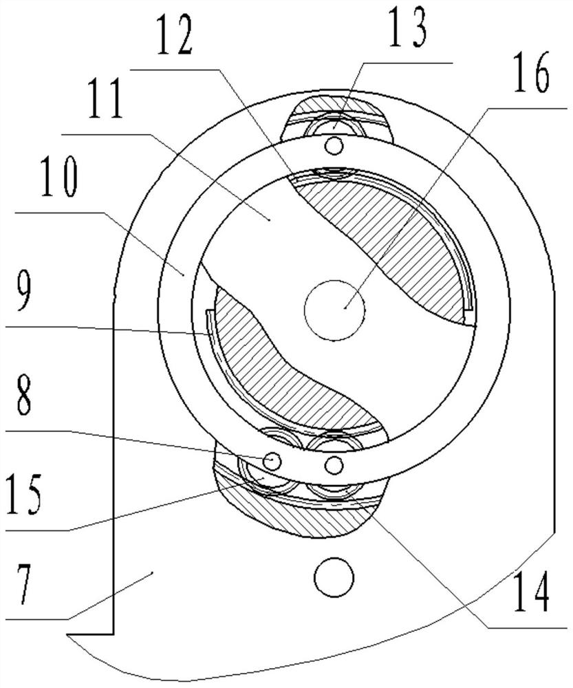
[0046] Such as Figure 5 , 8 , 9, there are two inner gear teeth segments 9 and outer gear teeth segments 12, and the inner gear teeth segments 9 and outer gear teeth segments 12 are alternately arranged on the circumference of the second sun gear 11, each The coverage angles of each inner gear tooth section 9 and each outer gear tooth section 12 are 90 degrees, and the inner gear tooth section 9 and the outer gear tooth section 12 are on a plane perpendicular to the axis 8 of the second sun gear 11 The projected dislocations form a 360 circle.

[0047] Compared with the first embodiment, the advantage of this embodiment is that the swing range of the crank body 7 is smaller, and the unnecessary wear on the plunger of the oil well pump is smaller.

Embodiment 3

[0049] The difference between the embodiment and the first embodiment lies in that the numbers of the inner gear teeth segments 9 and the outer gear teeth segments 12 are different.

[0050] Such as Figure 5 , 10 , 11, there are two inner gear tooth sections 9 and outer gear tooth sections 12, and the inner gear tooth sections 9 and the outer gear tooth sections 12 are arranged alternately on the circumference of the second sun gear 11, each The coverage angles of each inner gear tooth section 9 and each outer gear tooth section 12 are 90 degrees, and the inner gear tooth section 9 and the outer gear tooth section 12 are on a plane perpendicular to the axis 8 of the second sun gear 11 The projected dislocations form a 360 circle.


PUM


Abstract

The invention provides a pumping unit capable of achieving intermittent pumping through non-full-cycle motion of a crank without shutdown, and relates to the technical field of oil field oil extraction equipment. The pumping unit comprises a motor, a speed reducer, a crank assembly, a connecting rod, a walking beam and a support, wherein the motor is connected with an input shaft of the speed reducer through a belt transmission mechanism, the end part of the crank assembly is installed on an output shaft of the speed reducer and is driven by the speed reducer to rotate, the middle of the walking beam is hinged to the top end of the support, and the upper end and the lower end of the connecting rod are hinged to the tail part of the walking beam and the crank assembly respectively; and the crank assembly comprises a gear frame, a conventional gear train, an intermittent pumping gear train, a crank main body and a switching mechanism, wherein the gear frame, the conventional gear train and the intermittent pumping gear train are all installed in a circular hole in the center of the crank main body. According to the pumping unit, the crank can swing by a small amplitude through a special mechanism, the small-amplitude swing is equivalent to greatly reducing the stroke of the pumping unit, so that the oil pumping speed is greatly reduced, the oil pumping speed is greatly smaller than the seepage speed of underground liquid, and therefore dry pumping of an oil well pump is avoided.

Description

technical field [0001] The invention belongs to the technical field of oil production equipment in oilfields, and in particular relates to a pumping unit which realizes intermittent pumping through non-full circular motion of a crank without stopping. Background technique [0002] The so-called intermittent pumping means: in oilfield production, with the continuous exploitation of oil wells, the seepage speed of downhole liquid will continue to decrease. Stop working, and then start the oil well pump after the accumulation of downhole fluid, and repeat this process to match the downhole fluid volume with the pumping speed of the pumping unit, and prevent the phenomenon of "dry pumping" from damaging the oil well pump. [0003] In the prior art, since the stroke of the pumping unit cannot be adjusted in a wide range, the downhole oil pump can only be stopped by shutting down the pumping unit, but the complete shutdown of the pumping unit will make the liquid in the tubing nea...

Claims


Application Information

Patent Timeline
Patent Type & Authority Applications(China)
IPC IPC(8): E21B43/12
CPCE21B43/127
Inventor 于婷婷
Owner 于婷婷
Why Eureka
Try Eureka