GVV valve pressure maintaining structure and GVV valve

A pressure cylinder and valve body technology, applied in the direction of valve housing structure, valve details, safety valves, etc., can solve the problems of installation space environment restrictions, increase the overall structure height, etc., achieve oil and gas separation, reduce valve body height, and save energy. effect of space

Pending Publication Date: 2020-04-10
JIANGSU AOLIWEI SENSING TECH
View PDF1 Cites 0 Cited by
  • Summary
  • Abstract
  • Description
  • Claims
  • Application Information

AI Technical Summary

Problems solved by technology

A high-tightness fuel tank dump valve is disclosed in the prior art, and its publication number is: CN208859010U. The space environment creates constraints

Method used


Image

  • GVV valve pressure maintaining structure and GVV valve
  • GVV valve pressure maintaining structure and GVV valve
  • GVV valve pressure maintaining structure and GVV valve

Examples


Embodiment 1

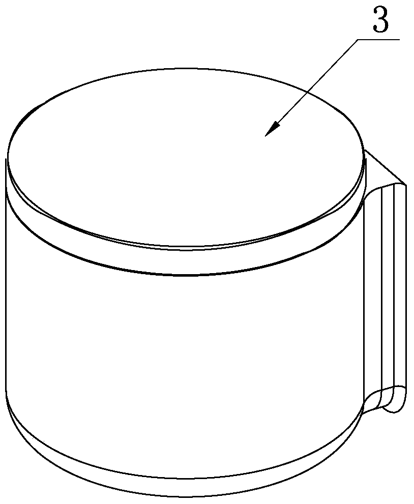
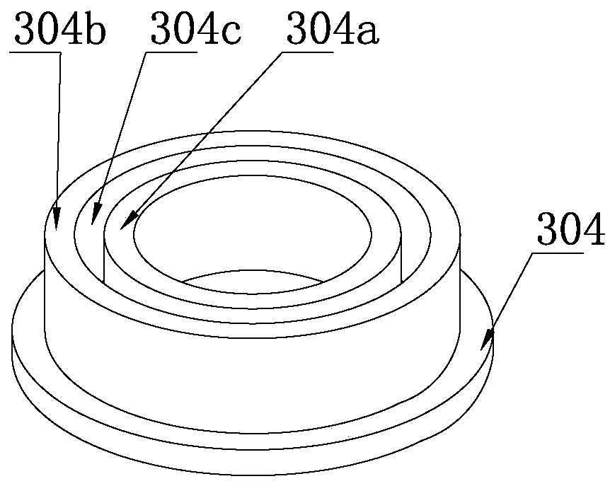
[0025] Such as Figure 1-4 The shown pressure maintaining structure of a GVV valve includes a pressure maintaining cylinder 308 arranged vertically, a cavity is provided inside the pressure maintaining cylinder 308, and an air inlet 301 communicating with the cavity is opened at the bottom of the pressure maintaining cylinder 308. The side of the barrel 308 is provided with an exhaust port 302 that communicates with the cavity. The top edge of the air inlet 301 extends upwards to form a boss 303. Ventilation groove 307, the movable part 304 that can move up and down is provided with in the cavity, and movable part 304 is in order to control the airflow flow between air inlet 301 and exhaust port 302, and movable part 304 is disc-shaped structure, and movable part 304 A spring 305 is arranged between the top wall of the cavity, and the movable part 304 is in contact with the boss 303 through the spring 305, and the disk-shaped movable part 304 realizes the airflow between the a...

Embodiment 2

[0027] Such as Figure 5-7 The shown pressure maintaining structure of a GVV valve includes a pressure maintaining cylinder 308 arranged vertically, a cavity is provided inside the pressure maintaining cylinder 308, and an air inlet 301 communicating with the cavity is opened at the bottom of the pressure maintaining cylinder 308. The side of the barrel 308 is provided with an exhaust port 302 that communicates with the cavity. The top edge of the air inlet 301 extends upwards to form a boss 303. Ventilation groove 307, the movable part 306 that can move up and down is arranged in the cavity, and movable part 306 is in order to control the air flow between air inlet 301 and exhaust port 302, and movable part 306 is cylindrical structure, and cylindrical movable part 306 realizes the air flow control between the air inlet 301 and the exhaust port 302 by its own weight.

Embodiment 3

[0029] Such as Figure 8 A new type of side exhaust GVV valve is shown, including a float 2 arranged in the valve body 1, the top of the valve body 1 is provided with an air inlet 1a, and the top of the valve body 1 extends to the side to form a side exhaust pipe 4 , the side exhaust pipe 4 communicates with the inside of the valve body 1 through the air inlet 1a, the end of the side exhaust pipe 4 is connected with an exhaust port, and the side exhaust pipe 4 is provided with a pressure-holding structure 3; the pressure-holding structure 3 includes a vertical The pressure-holding cylinder 308 arranged vertically, the interior of the pressure-holding cylinder 308 is provided with a cavity, the bottom of the pressure-holding cylinder 308 is provided with an air inlet 301 communicating with the cavity, and the side of the pressure-maintaining cylinder 308 is provided with an exhaust port connected to the cavity. Inlet 302, the top edge of the air inlet 301 extends upwards to for...


PUM


Abstract

The invention discloses a GVV valve pressure maintaining structure comprising a vertically arranged pressure maintaining barrel. A cavity is formed in the pressure maintaining barrel. An air inlet communicating with the cavity is formed in the bottom of the pressure maintaining barrel. An exhaust opening communicating with the cavity is formed in the side of the pressure maintaining barrel. The top edge of the air inlet extends upwards to form a boss. A ventilation notch is formed in the boss. At least one ventilation groove is formed in the inner wall of the pressure maintaining barrel. A movable part capable of moving up and down is arranged in the cavity and is used for controlling the airflow quantity between the air inlet and the exhaust opening. High-pressure pressure control can beachieved through the pressure maintaining structure, the pressure maintaining structure of the GVV valve is arranged laterally, the height of a valve body is lowered, space is saved, and the pressuremaintaining structure can be used in an automobile fuel tank.

Description

technical field [0001] The invention relates to a refueling control valve, in particular to a fuel tank exhaust valve. Background technique [0002] The fuel tank exhaust valve is installed on the top of the fuel tank assembly. In the traditional fuel tank exhaust valve technology, when the vehicle is running normally, the exhaust valve is always open to discharge fuel vapor. However, when the vehicle is dumped or overturned, the exhaust valve is automatically closed. . Exhaust valve in National VI technology: Under normal circumstances, fuel vapor is allowed to flow from the fuel tank to the carbon tank to prevent excessive positive pressure in the fuel tank; during work and refueling, if the pressure in the fuel tank is high enough, the head valve is opened to allow More fuel vapor flows from the fuel tank to the carbon canister; when the carbon canister is desorbed, fresh air is allowed to replenish into the fuel tank through the carbon canister to prevent excessive nega...

Claims


Application Information

Patent Timeline
Patent Type & Authority Applications(China)
IPC IPC(8): F16K17/04F16K27/02G05D16/16
CPCF16K17/04F16K27/02G05D16/166
Inventor 孙海鑫李冬梅田新仿吴晓东焦磊李艮春
Owner JIANGSU AOLIWEI SENSING TECH
Why Eureka
Try Eureka