
Device and method for detecting whether focusing of tower-type solar power generation system is precise

A tower-type solar energy and power generation system technology, which is applied in the direction of testing optical performance, can solve the problems of time-consuming and troublesome, and achieve the effects of low cost, improved correction efficiency, and convenient large-scale application

Pending Publication Date: 2020-04-10
何开浩
View PDF0 Cites 0 Cited by
  • Summary
  • Abstract
  • Description
  • Claims
  • Application Information

AI Technical Summary

Problems solved by technology

However, since there are hundreds, thousands, or even thousands of heliostats, it is very troublesome and time-consuming to perform an operation on each heliostat in order to perform a deflection correction operation.

Method used


Image

  • Device and method for detecting whether focusing of tower-type solar power generation system is precise
  • Device and method for detecting whether focusing of tower-type solar power generation system is precise
  • Device and method for detecting whether focusing of tower-type solar power generation system is precise

Examples


Embodiment 1

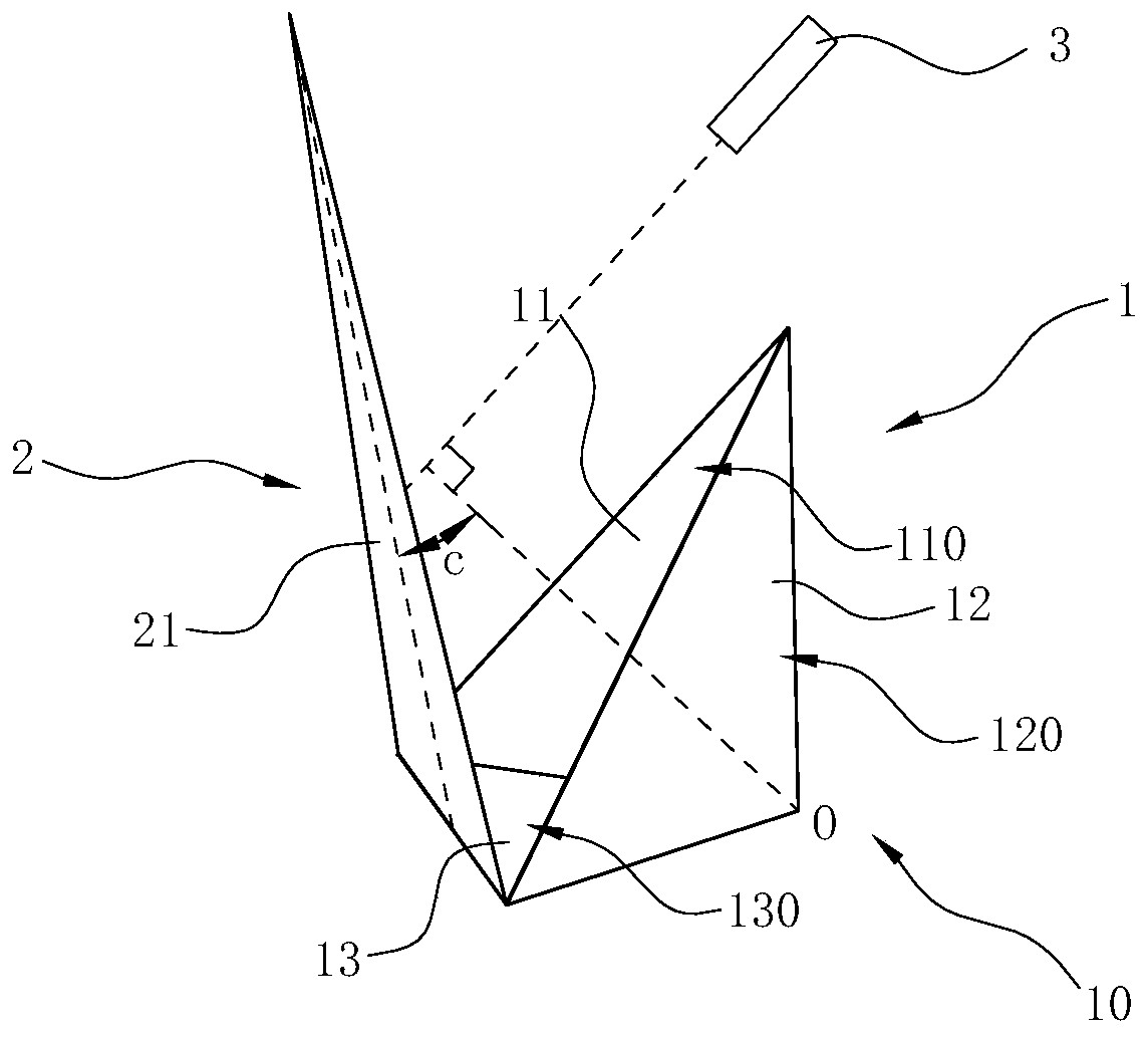
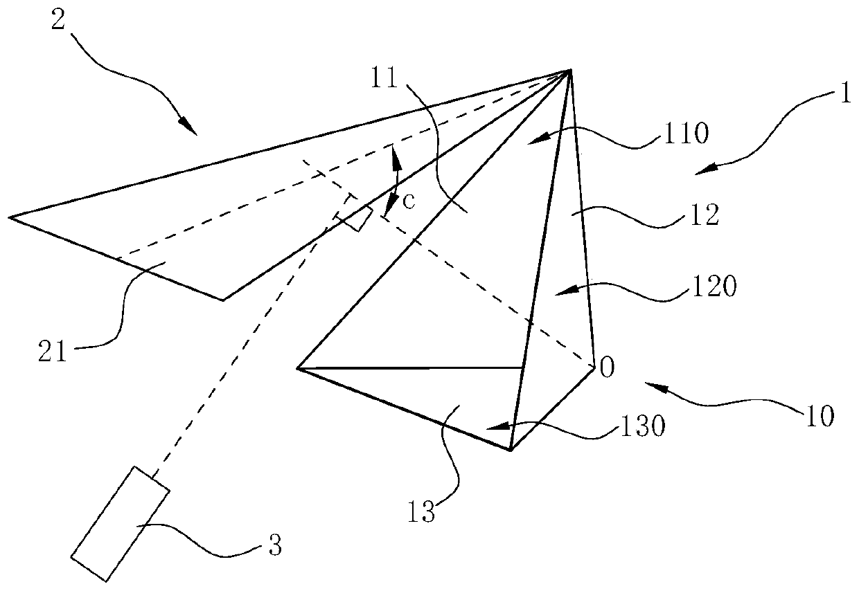
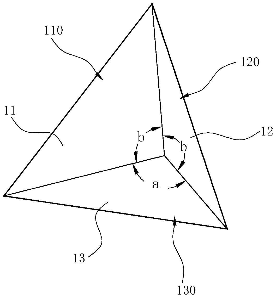
[0036] like Figure 1~3 As shown, the device for detecting whether the focus of the tower solar power generation system is accurate in this embodiment includes a first detection body 1 and a second detection body 2. The first detection body 1 has a first detection body that can reflect light and allow light to pass through. A plane 11, a second plane 12 and a third plane 13, the first plane 11 and the second plane 12 are arranged vertically and form an included angle a of 90 degrees, and the third plane 13 is arranged horizontally with the first plane 11, The second planes 12 all form an included angle b of 90 degrees, and the first plane 11 , the second plane 12 and the third plane 13 intersect at a point O to form a pyramid structure 10 protruding backward. The second detection body 2 has a fourth plane 21 that can both reflect light and allow light to pass through. The fourth plane 21 is obliquely arranged on the front side of the first detection body 1 away from point O. T...

Embodiment 2

[0045] The difference between this embodiment and embodiment 1 is:

[0046] like Figure 4~7 As shown, the first detection body 1' and the second detection body 2' of this embodiment are integrally formed to form an integral solid structure, the solid structure is made of transparent or translucent materials, such as polyester carbonate, glass, Resin, nylon, acrylic, polarizing material, etc.

[0047] When the first detection body 1' and the second detection body 2' are made into an integrated solid structure, there is still strong refraction of the light, which causes the scene behind the pyramid structure 10' to be impossible to observe. Therefore, in the first detection body 1 'The rear side is provided with a third detection body 4 that can reflect light and allow light to pass through. The front side of the third detection body 4 is recessed inwardly to form a pyramid-shaped cavity 40 that can wrap the pyramid structure therein. The third detection body The rear side of...


PUM


Abstract

The invention relates to a device and a method for detecting whether focusing of a tower-type solar power generation system is precise. The device comprises a first detection body and a second detection body, wherein the first detection body has a first plane, a second plane and a third plane which can reflect light rays and allow the light rays to penetrate through, and the first plane, the second plane and the third plane are arranged at 90 degrees and intersect at a point O; and the second detection body has a fourth plane which can reflect light and allow the light to penetrate through, and the fourth plane is obliquely arranged on the front side, away from the point O, of the first detection body. According to the device and the method, the reflection and light transmission principlesof light are fully utilized, the irradiation direction of solar rays is fed back by means of images of the sun, whether focusing of a heliostat is precise or not can be directly judged through judging whether the solar images are aligned with a heat collector of the tower-type solar power generation system, the detection is very intuitive and convenient, the detection time is greatly saved, and the correction efficiency is improved; and the device is simple in structure, low in cost, and convenient to realize large-scale application.

Description

technical field [0001] The invention relates to a device and method for detecting whether the focus of a tower solar power generation system is accurate. Background technique [0002] Solar energy is a kind of energy with low distribution density, intermittent and spatial distribution changing all the time, which is very different from the conventional energy we are familiar with in our life, which puts forward higher requirements for the collection and utilization of solar energy. At present, the solar water heater is the most widely utilized solar energy, but it can only meet the needs of people's daily life, the degree of heating of water is limited, and cannot meet the requirements of high-temperature hot water and steam in industry. In order to meet people's higher requirements for solar thermal utilization, it is required that solar collectors can absorb solar radiation energy more effectively. [0003] Common solar thermal power generation methods include dish type, ...

Claims


Application Information

Patent Timeline
Patent Type & Authority Applications(China)
IPC IPC(8): G01M11/02
CPCG01M11/02
Inventor 何开浩
Owner 何开浩
Learn More