Flight time obtaining method and device and electronic device

A time-of-flight and acquisition method technology, applied to radio wave measurement systems, instruments, etc., can solve problems such as obvious interference, affecting ranging results, and the impact of time-of-flight acquisition results

Active Publication Date: 2020-04-10
QINGDAO PICO TECH CO LTD
View PDF13 Cites 2 Cited by
  • Summary
  • Abstract
  • Description
  • Claims
  • Application Information

AI Technical Summary

Problems solved by technology

Especially when the object that needs to be measured is far away, and the object that produces multi-path reflection is close, because the energy reflected by the nearby ob

Method used


Image

  • Flight time obtaining method and device and electronic device
  • Flight time obtaining method and device and electronic device
  • Flight time obtaining method and device and electronic device

Examples


Embodiment Construction

[0048] Various exemplary embodiments of the present invention will now be described in detail with reference to the accompanying drawings. It should be noted that the relative arrangements of components and steps, numerical expressions and numerical values ​​set forth in these embodiments do not limit the scope of the present invention unless specifically stated otherwise.

[0049] The following description of at least one exemplary embodiment is merely illustrative in nature and in no way taken as limiting the invention, its application or uses.

[0050] Techniques, methods and devices known to persons of ordinary skill in the relevant art may not be discussed in detail, but where appropriate, techniques, methods and devices should be considered part of the description.

[0051] In all examples shown and discussed herein, any specific values ​​should be construed as exemplary only, and not as limitations. Therefore, other instances of the exemplary embodiment may have differ...


PUM


Abstract

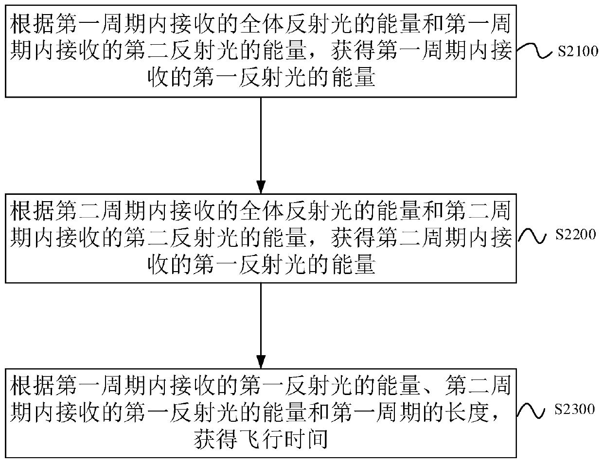
The invention relates to a flight time obtaining method and device and an electronic device. The method comprises the following steps: obtaining the energy of first reflected light received in a firstperiod according to the energy of all reflected light received in the first period and the energy of second reflected light received in the first period; obtaining the energy of the first reflected light received in the second period according to the energy of the whole reflected light received in the second period and the energy of the second reflected light received in the second period; and obtaining the flight time according to the energy of the first reflected light received in the first period, the energy of the first reflected light received in the second period and the length of the first period.

Description

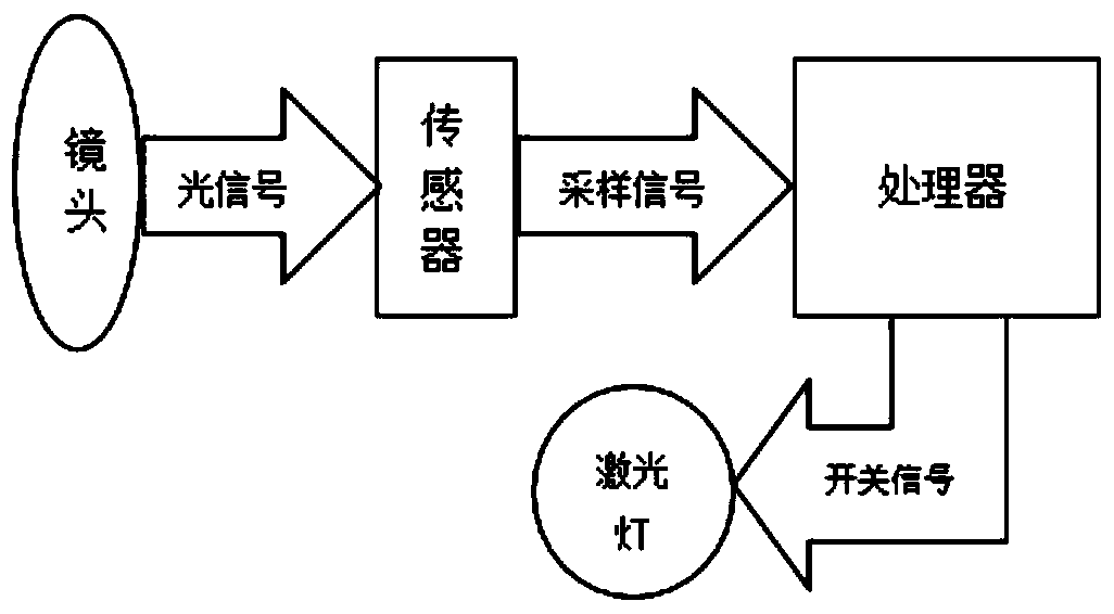
technical field [0001] The present invention relates to the technical field of depth information measurement, and more specifically, to a time-of-flight acquisition method, a time-of-flight acquisition device, an electronic device, and a computer-readable storage medium. Background technique [0002] TOF (Time of Flight, Time of Flight) is a depth information measurement technology. Its principle can be briefly summarized as follows: first, the infrared laser emits laser light, and when the laser light encounters an obstacle and reflects back, it is received by the lens and converted into an electrical signal on the sensor , according to the time of light emission and reception, the time of flight of light in space is obtained, and the distance to be measured is obtained. [0003] Ideally, the light received by each pixel of the sensor is directly reflected by the object that needs to be measured, but in reality, the light received by the sensor pixel is also reflected throu...

Claims


Application Information

Patent Timeline
IPC IPC(8): G01S7/48
CPCG01S7/4808G01S7/48
Inventor 舒玉龙郑光璞吴涛
Owner QINGDAO PICO TECH CO LTD
Why Eureka
Try Eureka