K-mirror optical system adjustment method

A technology of optical system and adjustment method, which is applied in optics, optical components, instruments, etc., can solve the problem of low accuracy of K-mirror installation and adjustment method, and achieve the effects of universality, improved installation accuracy, and simple installation and adjustment method

Active Publication Date: 2020-04-10
HUAZHONG UNIV OF SCI & TECH
View PDF11 Cites 4 Cited by
  • Summary
  • Abstract
  • Description
  • Claims
  • Application Information

AI Technical Summary

Problems solved by technology

[0004] Aiming at the defects of the prior art, the object of the present invention is to provide a method for adjusting the optical system of the K-mirror, aiming at solving the problem that the accuracy of the existing method for adjusting the K-mirror is not high

Method used


Image

  • K-mirror optical system adjustment method
  • K-mirror optical system adjustment method
  • K-mirror optical system adjustment method

Examples


Embodiment Construction

[0031] In order to make the object, technical solution and advantages of the present invention clearer, the present invention will be further described in detail below in conjunction with the accompanying drawings and embodiments. It should be understood that the specific embodiments described here are only used to explain the present invention, not to limit the present invention. In addition, the technical features involved in the various embodiments of the present invention described below can be combined with each other as long as they do not constitute a conflict with each other.

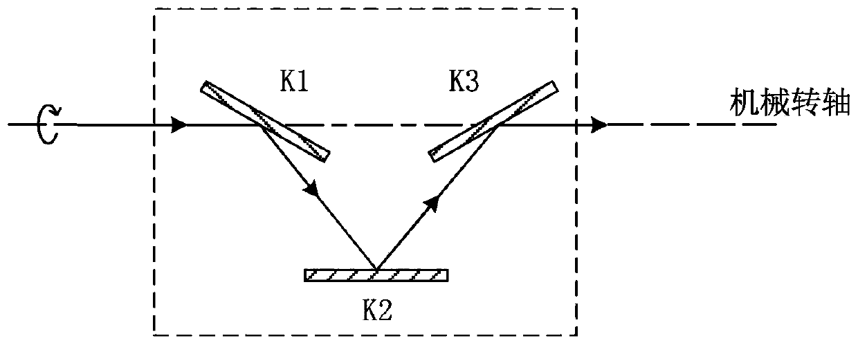
[0032] The schematic diagram of the components of the K-mirror optical system is as follows: figure 1 As shown, the optical system is composed of three optical mirrors, which are marked as K1, K2 and K3 from left to right; the optical system has a rotation axis, which is shown as the mechanical rotation axis in the figure.

[0033] For realizing the purpose of the present invention, the K mirro...


PUM


Abstract

The invention discloses a K-mirror optical system adjustment method, and belongs to the field of optical element adjustment. The method comprises the following steps: S1, an optical reference of a K-mirror optical system is established by using an optical parallel plate and an interferometer; S2, the position of a K2 mirror is adjusted by means of a pentaprism to make the surface of the K2 mirrorto be parallel to a mechanical rotating shaft of the K-mirror optical system; and S3, the K3 mirror is placed according to the mechanical plane position, then a K1 mirror is placed and the position ofthe K1 mirror is adjusted, so that zero-order fringes are formed in the interferometer after emergent light of the interferometer is reflected by the K1 mirror, the K2 mirror, a K3 mirror and the optical parallel plate. The method has the advantages of high adjustment precision, simple adjustment method, universality of adjustment tools and the like, and a corresponding optical reference is reserved in the adjusted K-mirror optical system to be used as an optical interface for butt joint of the K-mirror optical system and a subsequent optical system.

Description

technical field [0001] The invention belongs to the field of optical element installation and adjustment, and more specifically relates to an installation and adjustment method of a K-mirror optical system. Background technique [0002] With the rapid development of modern science and technology, the performance of the telescope has made great progress; with the improvement of the performance of the telescope, astronomy has also experienced a huge leap, and the requirements for various observations have also gradually increased. More large-scale horizon telescopes get applied. In the process of tracking the target of a large horizon-type optical astronomical telescope, the relative rotation of the silo in the optical path will cause the field of view to rotate around the center, which is called the rotation of the image square field of view. The horizon telescope is stationary relative to the horizon meridian, and the horizon meridian rotates continuously relative to the po...

Claims


Application Information

Patent Timeline
Patent Type & Authority Applications(China)
IPC IPC(8): G02B27/62
CPCG02B27/62
Inventor 闫力松莫言晁联盈陈晓晨马冬林
Owner HUAZHONG UNIV OF SCI & TECH
Why Eureka
Try Eureka