Side span shape finding method adopting resultant force control in horizontal plane

A horizontal plane and side span technology, applied in data processing applications, instruments, electrical digital data processing, etc., can solve the problem of lateral inclination of bridge towers, tension of girder beams of portal towers, failure to obtain theoretical vertices of loose cable saddles or reasonable transverse direction of anchor points Position and other issues, to achieve the effect of simple design

Active Publication Date: 2020-04-10
CHINA MAJOR BRIDGE ENERGINEERING
View PDF6 Cites 11 Cited by
  • Summary
  • Abstract
  • Description
  • Claims
  • Application Information

AI Technical Summary

Problems solved by technology

[0004] However, the above method has the following problems: 1. There is still a lateral unbalanced force at the top of the tower. For a single-column tower, it will cause the bridge tower to tilt laterally, and for a portal tower, it will cause the beam to be pulled; 2. The alignment of the side span and the alignment of the main span There is a knuckle at the top, and the design of the saddle groove curve is extremely complicated; 3. It is impossible to obtain a reasonable lateral position of the theoretical vertex or anchor point of the loose cable saddle

Method used


Image

  • Side span shape finding method adopting resultant force control in horizontal plane
  • Side span shape finding method adopting resultant force control in horizontal plane
  • Side span shape finding method adopting resultant force control in horizontal plane

Examples


Embodiment

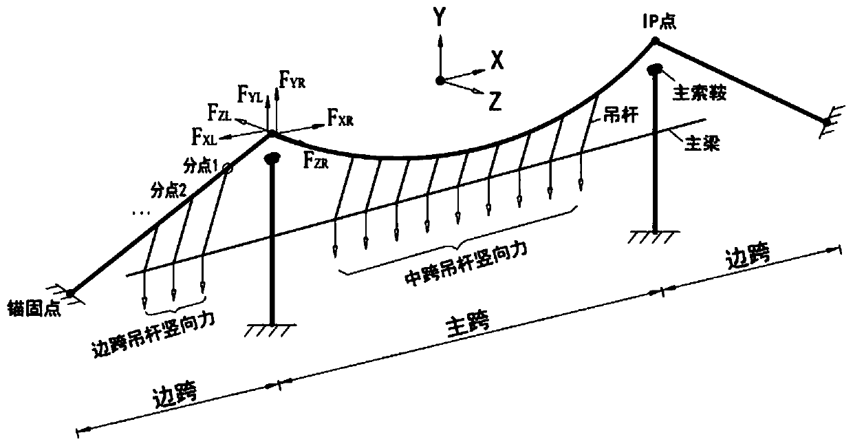
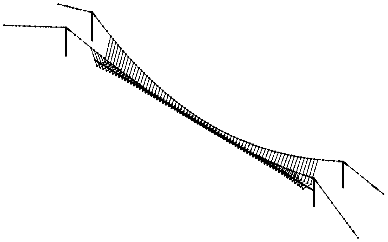
[0028] see figure 1 , figure 2 and image 3 As shown, the embodiment of the present invention provides a side-span form-finding method using resultant force control in the horizontal plane, including the following steps:

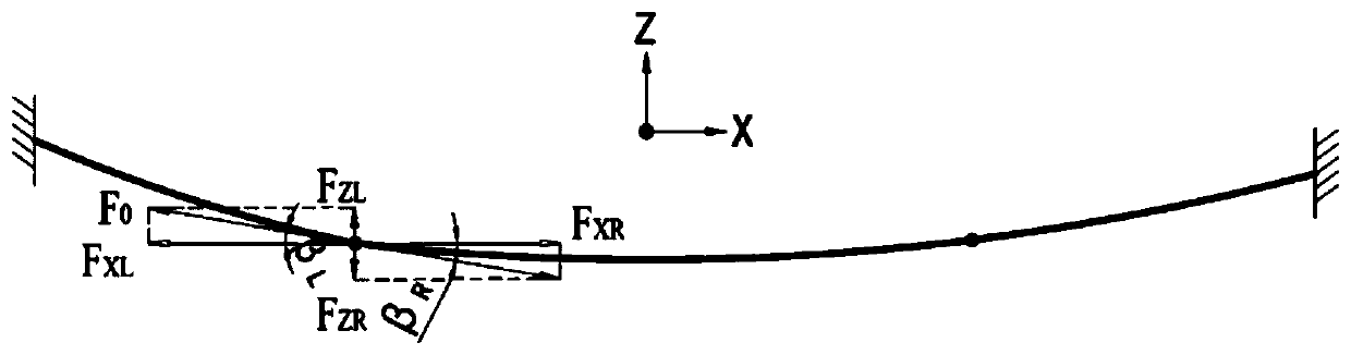
[0029] Step 1. According to the given mid-span rise-span ratio, use the spatial cable analytical form-finding method to iteratively obtain the mid-span line shape and mid-span theoretical apex ( figure 1 Longitudinal force F of mid-span main cable at mid-span point) XR , vertical force F YR , Lateral force F ZR , calculate the angle β between the resultant force in the horizontal plane at the end of the mid-span and the longitudinal axis R =atan(F ZR / F XR ).

[0030] Step 2. Let the longitudinal component F of the side-span main cable at the theoretical apex of the main saddle be XL =-F XR , the angle β between the resultant force in the horizontal plane at the end of the side span and the longitudinal axis L = β R . In step 2 of this embodime...


PUM


Abstract

The invention discloses a side span shape finding method adopting resultant force control in a horizontal plane. The method comprises the following steps: taking a vertical component force of a side span main cable at a theoretical vertex as an iterative variable, taking a vertical coordinate of the theoretical vertex or an anchoring point at a splay saddle as an iterative target, adding a new control item, i.e., an included angle between a resultant force in a horizontal plane and a longitudinal axis of a side span end part, and carrying out loop iteration on a side span cable system until aprecision requirement is met. According to the side span shape finding method, it is guaranteed that the longitudinal component force and the transverse component force of the cable force on the towertop are equal, in other words, the resultant force in the horizontal plane is equal, the bridge tower can be completely vertical, the obtained side span line shape and the obtained middle span line shape do not have folded angles on the tower top, and the transverse coordinates of the theoretical vertex or the anchoring point of the splay saddle can be accurately calculated. When the bridge forming state of the space cable suspension bridge is determined, the side span shape finding method controlled by the resultant force in the horizontal plane is successfully applied to the design of a large canyon glass bridge with the main span of 430 m.

Description

technical field [0001] The invention relates to the technical field of reasonable alignment analysis of bridges in the design of suspension bridges, in particular to a form-finding method for side spans controlled by resultant force in a horizontal plane. Background technique [0002] The space cable suspension bridge is a three-dimensional cable system composed of the space main cable and the transversely inclined suspension cables. Compared with the planar cable suspension bridge, the space system greatly improves the lateral stiffness and torsional stiffness of the structure, and improves the dynamic stability of the structure. In addition, the space cable suspension bridge has a beautiful appearance and is being popularized and applied in municipal and scenic bridges, such as the Zhangjiajie Grand Canyon Glass Bridge. [0003] When designing a suspension bridge, the bridge alignment analysis should be carried out first to determine the reasonable bridge alignment. At pre...

Claims


Application Information

Patent Timeline
IPC IPC(8): G06F30/13G06Q50/08G06F119/14
CPCG06Q50/08
Inventor 万田保霍学晋陈佳高宗余王忠彬王东绪马润平刘芸欣
Owner CHINA MAJOR BRIDGE ENERGINEERING
Why Eureka
Try Eureka