A method, device, medium and equipment for optical fiber unidirectional time-frequency synchronization signal transmission

A technology of time-frequency synchronization and signal transmission, which is applied in the direction of multiplexing communication, optical multiplexing system, time division multiplexing system, etc., to achieve the effect of eliminating the effect of inherent delay

Active Publication Date: 2021-07-27
电信科学技术第五研究所有限公司
View PDF7 Cites 0 Cited by
  • Summary
  • Abstract
  • Description
  • Claims
  • Application Information

AI Technical Summary

Problems solved by technology

[0008] This application provides a method, device, medium and equipment for optical fiber one-way time-frequency synchronization signal transmission to solve the existing technical problems, so that on the condition that the isolated network side does not need to add time-frequency taming equipment, select a company with a close physical distance The network is used to import single-fiber co-fiber one-way low-loss high-precision time-frequency signals for the isolated network, and the time-frequency and frequency-consuming devices of the isolated network directly use the imported time-frequency electrical signals to synchronize time-frequency with the public network

Method used


Image

  • A method, device, medium and equipment for optical fiber unidirectional time-frequency synchronization signal transmission
  • A method, device, medium and equipment for optical fiber unidirectional time-frequency synchronization signal transmission
  • A method, device, medium and equipment for optical fiber unidirectional time-frequency synchronization signal transmission

Examples


specific Embodiment 1

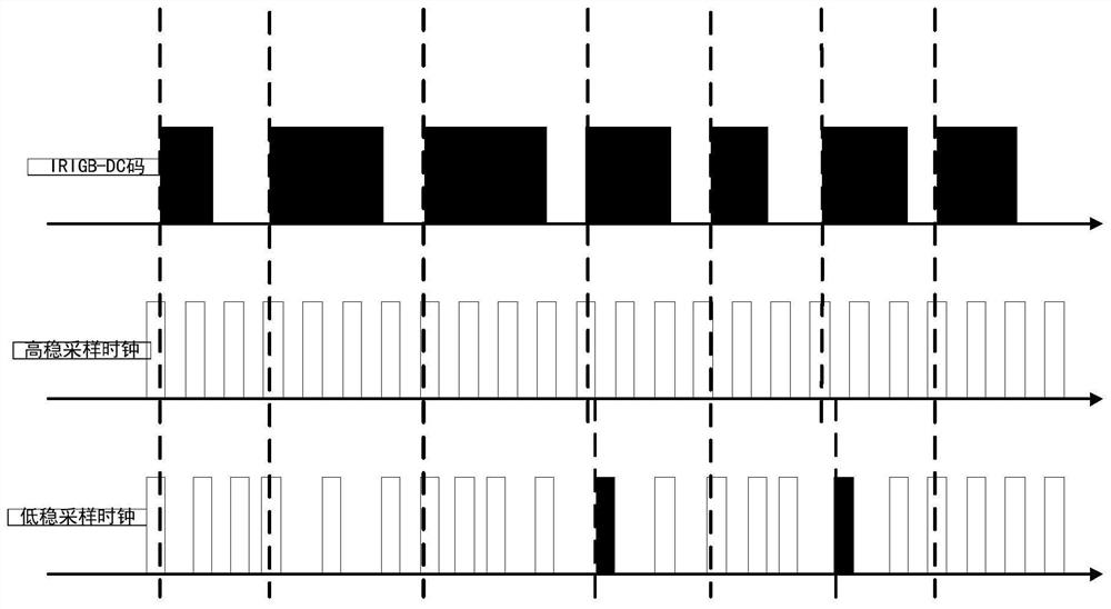
[0048] Depend on figure 2 It can be seen that when the IRIGB-DC code signal is sampled by the high-precision external clock input by the external clock interface of the photoelectric converter, there will be no phase jitter relative to the quasi-time delay of the high-precision time-frequency signal or the jitter is within an acceptable range.

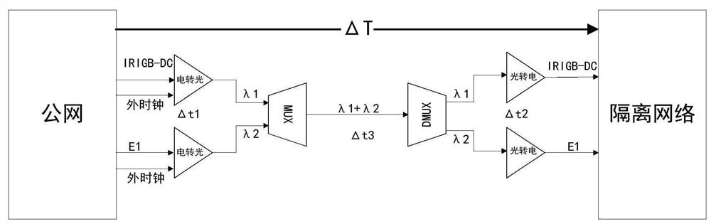
[0049] On the public network side, taking the short-term stability of ±0.03ppm external clock 10MHz input as an example, the phase jitter generated when a stable IRIGB-DC code electrical signal is extracted unidirectionally and converted into an optical signal does not exceed Δt1=±30ns.

[0050] On the isolated network side, the photoelectric converter works in the mode of extracting the line clock, and the jitter generated when converting this optical signal into an electrical signal does not exceed Δt2=±30ns.

[0051] At this time, the IRIGB-DC code electric signal is introduced into the isolated network user equipment, and the time...


PUM


Abstract

The present application discloses an optical fiber one-way time-frequency synchronization signal transmission method, device, medium and equipment. In this application, the high-precision time electrical signals and high-precision frequency electrical signals of the public network are converted into time optical signals and frequency optical signals through photoelectric converters; In a single optical fiber link; through the demultiplexer, the high-precision time optical signal and high-precision frequency optical signal are recovered from the single optical fiber link; the high-precision time optical signal and high-precision frequency optical signal are converted correspondingly through the photoelectric converter It is a high-precision time electrical signal and a high-precision frequency electrical signal. Under the condition that there is no need to add time-frequency taming equipment on the isolated network side, this application selects the public network with a close physical distance as the isolated network to import single-fiber, co-fiber, one-way, low-loss, high-precision time-frequency signals, and the isolated network uses time and frequency devices directly. Use the imported time-frequency electrical signal to perform time-frequency synchronization with the public network.

Description

technical field [0001] The present application relates to the field of optical fiber one-way time-frequency transmission, in particular, to a method, device, medium and equipment for optical fiber one-way time-frequency synchronization signal transmission. Background technique [0002] In some isolated networks, there are high requirements for network security. In order to prevent services in the network from being attacked or tampered with, it is necessary to physically isolate the isolated network and prohibit information exchange between certain isolated networks and the public network. However, the business operation of the isolated network requires time-frequency synchronization for support. [0003] To ensure physical isolation from the public network. At present, the method of time synchronization in an isolated network generally adopts independent synchronization of each node. [0004] The independent synchronization of each node generally uses independent time-fr...

Claims


Application Information

Patent Timeline
Patent Type & Authority Patents(China)
IPC IPC(8): H04J3/06H04J14/02
CPCH04J3/0617H04J3/0635H04J14/0227H04J14/0287
Inventor 黄嘉王茂凌何定高邓皓张骏杨张恒
Owner 电信科学技术第五研究所有限公司
Why Eureka
Try Eureka