Urea production process and production plant using co2 produced by oxy-combustion

A technology of oxygen-enriched combustion and production process, which is used in products, preparation of urea derivatives, chemical instruments and methods, etc., can solve the problem of inability to supply a variety of supplies, and achieve the effects of simplifying capture, increasing efficiency, and improving capacity

Active Publication Date: 2020-04-10
SAIPEM SPA
View PDF12 Cites 0 Cited by
  • Summary
  • Abstract
  • Description
  • Claims
  • Application Information

AI Technical Summary

Problems solved by technology

[0023] Furthermore, oxyfuel in general is not capable of feeding multiple supplies, whatever their nature, and oxyfuel in general can suffer from problems common to any burner related to variations in fuel flow

Method used


Image

  • Urea production process and production plant using co2 produced by oxy-combustion
  • Urea production process and production plant using co2 produced by oxy-combustion

Examples


Embodiment Construction

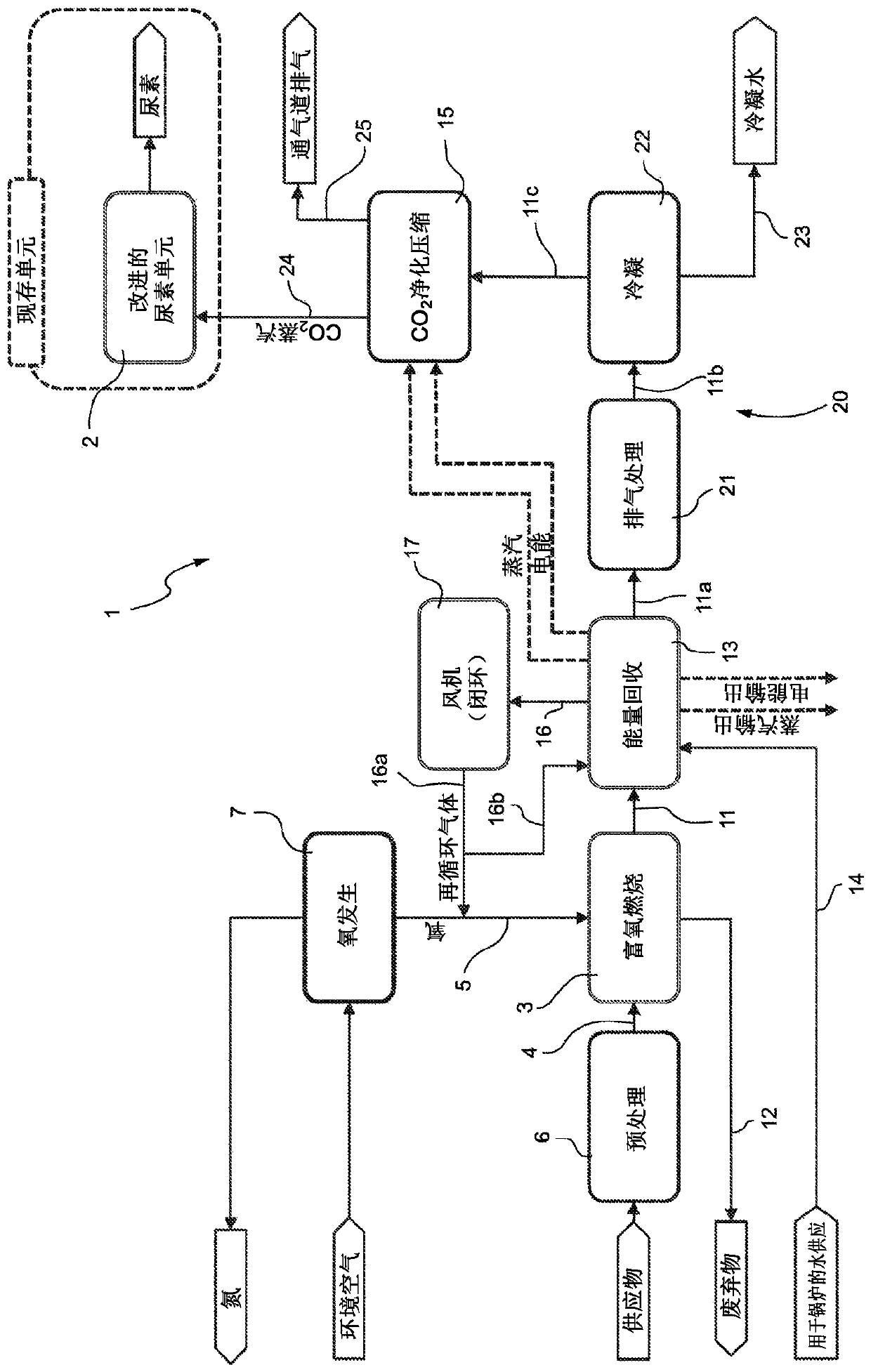
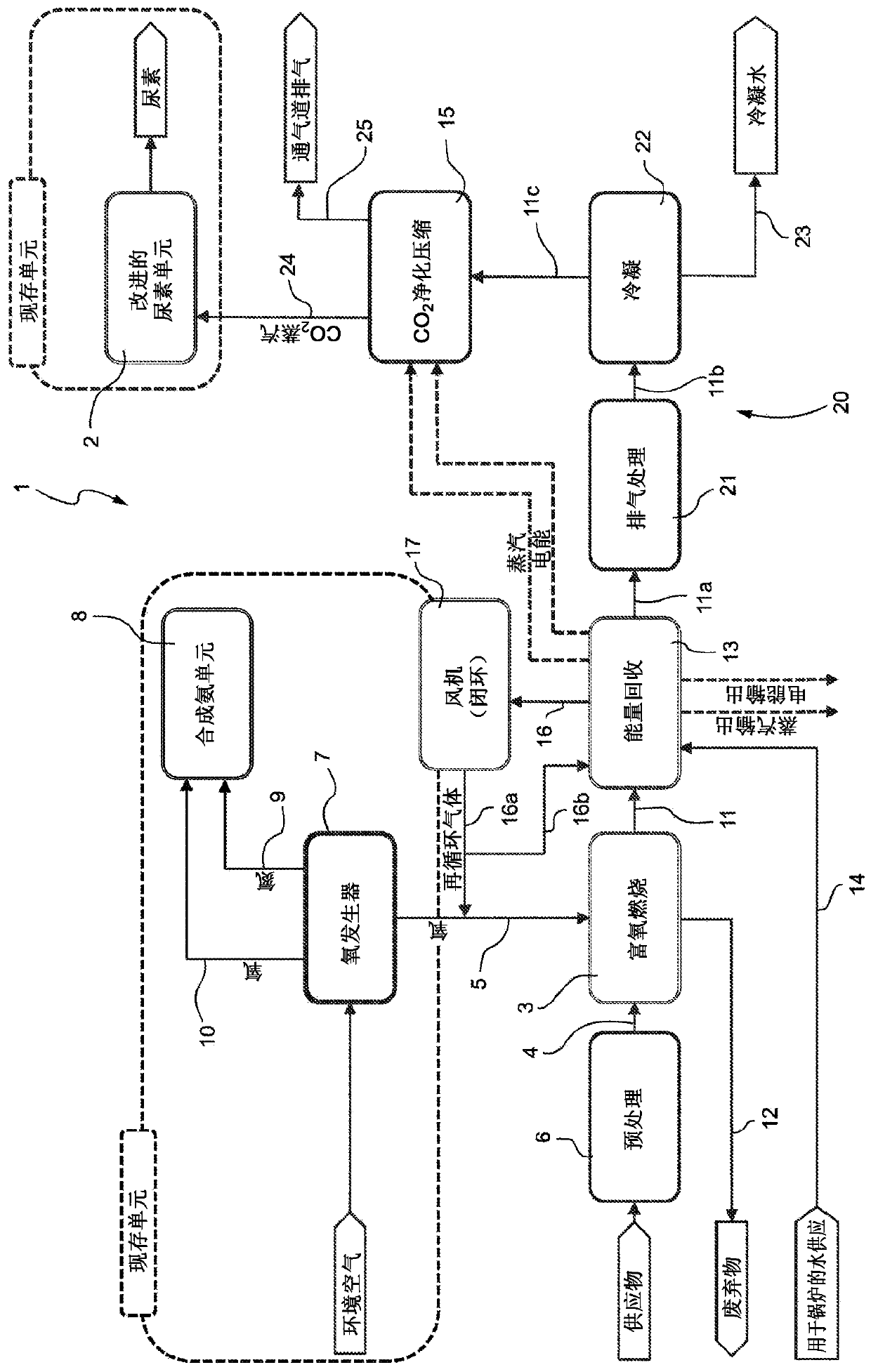
[0044] exist figure 1 Among them, 1 represents the urea production plant as a whole, which includes a urea unit 2, which is used to produce urea through the reaction of ammonia and carbon dioxide, and an oxygen-enriched combustion unit 3, which converts the carbon dioxide (CO2) produced in this unit 2 ) to the urea unit 2 for supplying feedstock to the urea synthesis reaction of ammonia and carbon dioxide.

[0045] The urea unit 2 (which can also be an existing unit, “enhanced” with the integration of the oxyfuel unit 3 ) is basically known per se and is therefore not described or shown in detail for the sake of simplicity.

[0046] The urea unit 2 in which the urea production process takes place can be of various types.

[0047] For example, but not necessarily, the urea unit 2 may be configured to take place in a conventional urea process known as the "SnamprogettiTM Urea Technology", but it should be understood that the invention is also applicable to other urea production...


PUM


Abstract

A urea production process comprises a step of synthesis of urea by reaction of ammonia and carbon dioxide, where at least part of the carbon dioxide for the urea reaction synthesis is produced in an oxy-combustion process; the oxy-combustion process is specifically a flameless oxy- combustion process.

Description

[0001] Citations to related applications [0002] This application claims priority from Italian Patent Application No. 102017000090748 filed on August 4, 2017, the disclosure of which is incorporated herein by reference. technical field [0003] The present invention relates to a urea production process and production plant using CO produced by oxy-combustion of supplied carbon 2 . [0004] There is an increasing need for environmental protection and especially careful monitoring of CO 2 emissions. [0005] Therefore, in various industrial sectors, the solutions adopted are characterized by seeking to increase energy efficiency and reduce pollutants and CO 2 emissions, for example, through CO 2 recirculation to reduce CO 2 emissions. Background technique [0006] An industrial urea production facility usually includes an ammonia plant and a urea plant in which the CO required for urea synthesis is recovered via process gas cleaned by known techniques 2 , and the CO 2...

Claims


Application Information

Patent Timeline
Patent Type & Authority Applications(China)
IPC IPC(8): C07C273/04
CPCC07C273/04C01C1/0488C07C273/10C07C273/16
Inventor 安德烈亚·赞比安科多纳托·蒙特罗内萝塞拉·波利齐马西米利亚诺·萨拉焦亚·乌萨伊
Owner SAIPEM SPA
Why Eureka
Try Eureka