Electronic braking system for an irrigation machine

An irrigation system and power technology, applied in the field of irrigation machines, can solve the problems of high failure rate, high corrosion rate and wear rate of mechanical brake or mechanism, high maintenance cost, etc.

Active Publication Date: 2020-04-10
VALMONT INDUSTIES INC
View PDF13 Cites 0 Cited by
  • Summary
  • Abstract
  • Description
  • Claims
  • Application Information

AI Technical Summary

Problems solved by technology

However, the weight and inertia of the drive tower may still be sufficient to allow the drive tower to continue moving an unacceptable distance, especially on sloping terrain, resulting in a "skid effect"
Additionally, the use of increased kinetic friction purely within the drive train creates unnecessary wear and heat within the drive train components and increases the energy consumption of the irrigation machine
Additionally, mechanical brakes or mechanisms are subject to high rates of corrosion and wear, especially in wet environments where irrigation machines are often found, resulting in high maintenance costs and high failure rates

Method used


Image

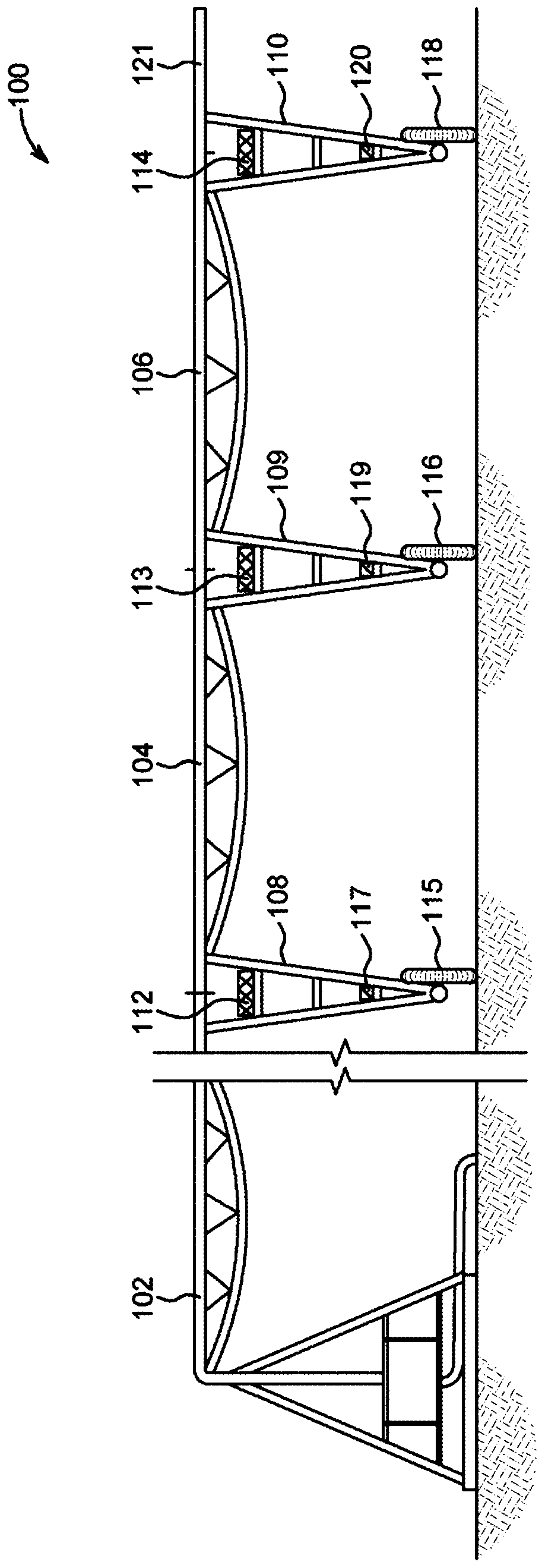
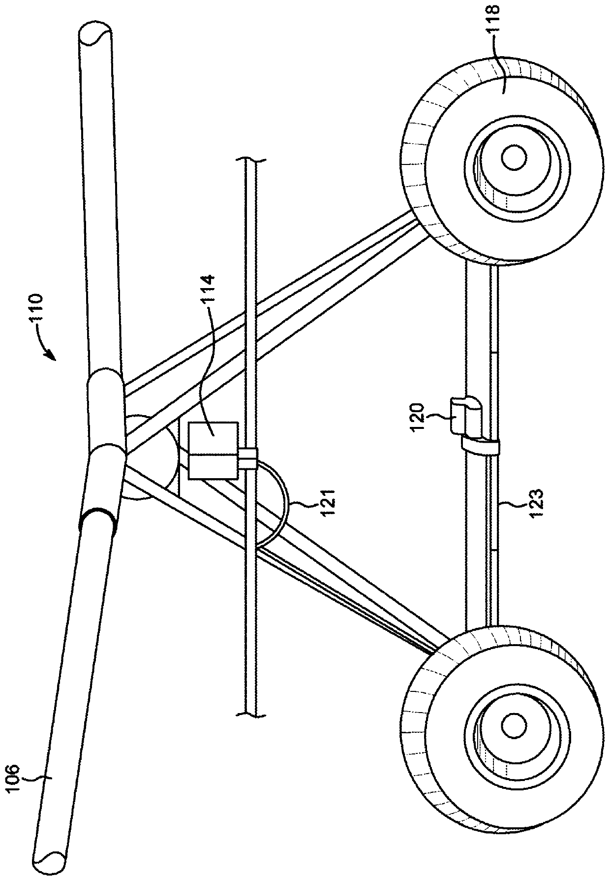
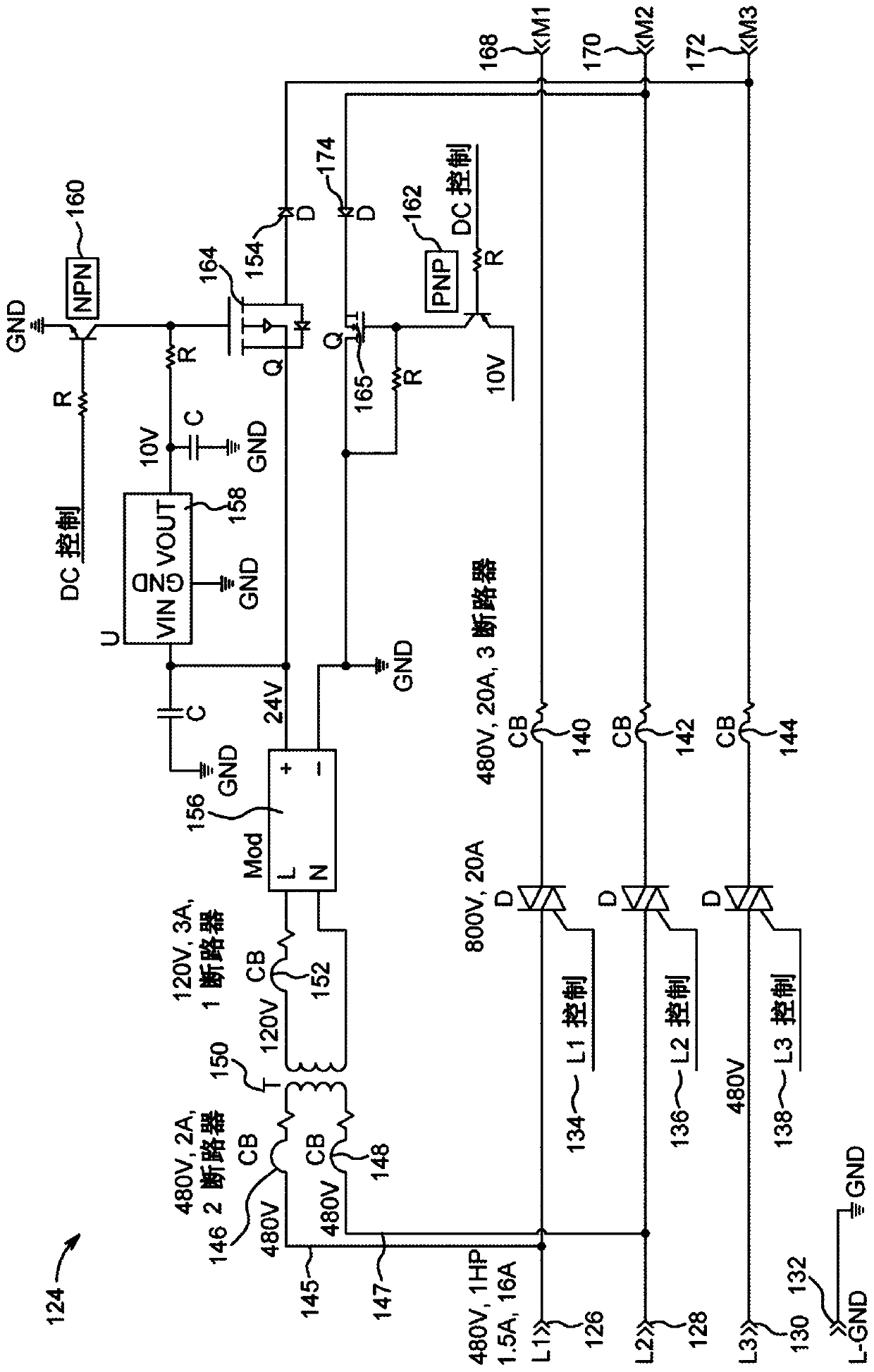
  • Electronic braking system for an irrigation machine
  • Electronic braking system for an irrigation machine
  • Electronic braking system for an irrigation machine

Examples


Embodiment Construction

[0019] Reference will now be made in detail to the exemplary embodiments of the present invention, examples of which are illustrated in the accompanying drawings. Wherever possible, the same reference numbers will be used throughout the drawings to refer to the same or like parts. The description, implementation and drawings should not be considered as limiting the scope of the claims. It should also be understood that throughout this disclosure, where a process or method is shown or described, the steps of the method may be performed in any order, repeatedly, iteratively or simultaneously, unless logically required otherwise. As used throughout this application, the word "may" is used in a permissive sense (ie, meaning "has the potential to") rather than a mandatory sense (ie, meaning "must").

[0020] Additionally, no example or illustration given herein should in any way be considered to restrict, limit or define an expression of any term or terms it uses. Instead, such e...


PUM


Abstract

The present invention provides an electronic braking system for an irrigation machine. According to an exemplary preferred embodiment, the present invention includes a drive controller which includesa power supplying circuit which signals an ON condition when a motive power request is input into the drive controller and an OFF condition when motive power is not input into the system. According toa further preferred embodiment, the present invention further includes a 3-phase induction motor connected to apply torque to a drive shaft which is connected to a least one drive wheel. According toa further preferred embodiment, the power supplying circuit supplies 480V AC of motive power to the drive motor when the drive controller signals the ON condition and 10-80V DC of non-motive power toat least one phase of the motor when the drive controller signals the OFF condition. According to a further preferred embodiment, the application of the DC current is applied immediately after the motive power is removed from the drive motor and the application of non-motive power brakes and prevents the drive shaft from turning until the DC current is removed.

Description

[0001] related application [0002] This application claims priority to U.S. Patent Application 16 / 038,859, filed July 18, 2018; this application claims priority to U.S. Provisional Application Serial No. 62 / 534,822, filed July 20, 2017; this application also claims Priority to U.S. Provisional Application Serial No. 62 / 572,803, filed October 16, 2017, the entirety of which is hereby incorporated by reference herein. technical field [0003] The present invention relates generally to irrigation machines and, more particularly, to electronic braking systems for irrigation machines. Background technique [0004] A modern field irrigation machine is a combination drive system and sprinkler system. Generally, these systems fall into two types according to the type of stroke they are designed to perform: center pivot and / or linear. [0005] Whether center-pivot or linear, common irrigation machines typically include overhead sprinkler irrigation systems consisting of several pi...

Claims


Application Information

Patent Timeline
Patent Type & Authority Applications(China)
IPC IPC(8): F16D59/00A61M3/02F16D121/26
CPCF16D63/002
Inventor 特蕾西·A·撒切尔基廷·戴斯
Owner VALMONT INDUSTIES INC
Why Eureka
Try Eureka