Steering system for work machinery

A technology of operating machinery and driving systems, applied in the field of driving systems, can solve the problems of increased cost of antenna driving systems, and achieve the effect of reducing costs

Active Publication Date: 2021-11-02
J THINK CORP
View PDF6 Cites 0 Cited by
  • Summary
  • Abstract
  • Description
  • Claims
  • Application Information

AI Technical Summary

Problems solved by technology

[0004] However, even if the antenna is not stolen, there is a problem that the cost of the driving system of the work machine increases due to the high price of the antenna.

Method used


Image

  • Steering system for work machinery
  • Steering system for work machinery
  • Steering system for work machinery

Examples


Embodiment Construction

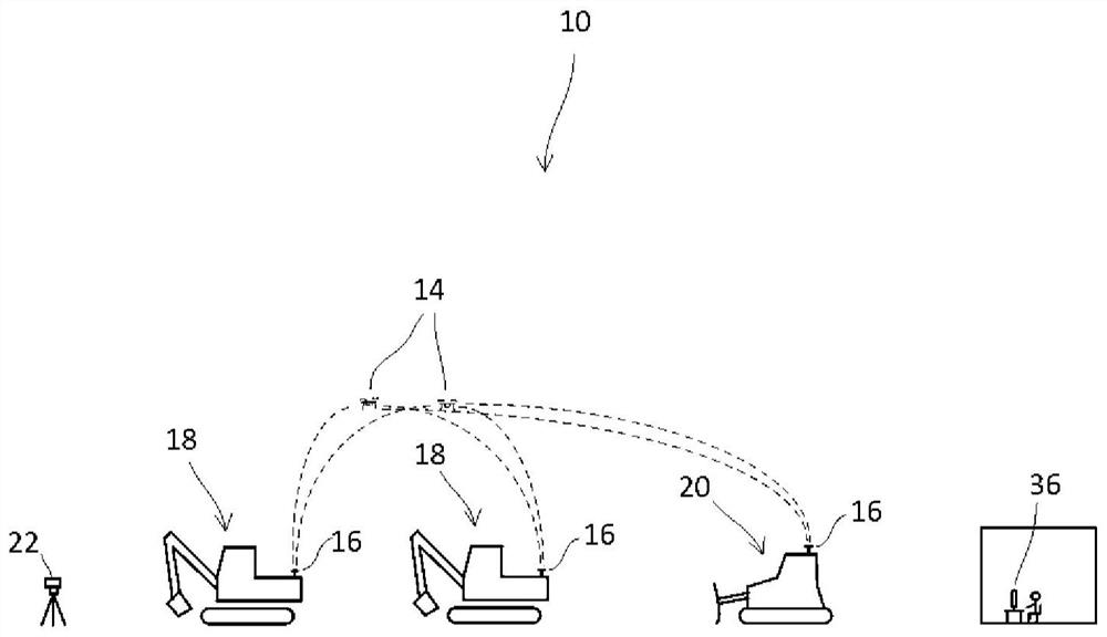
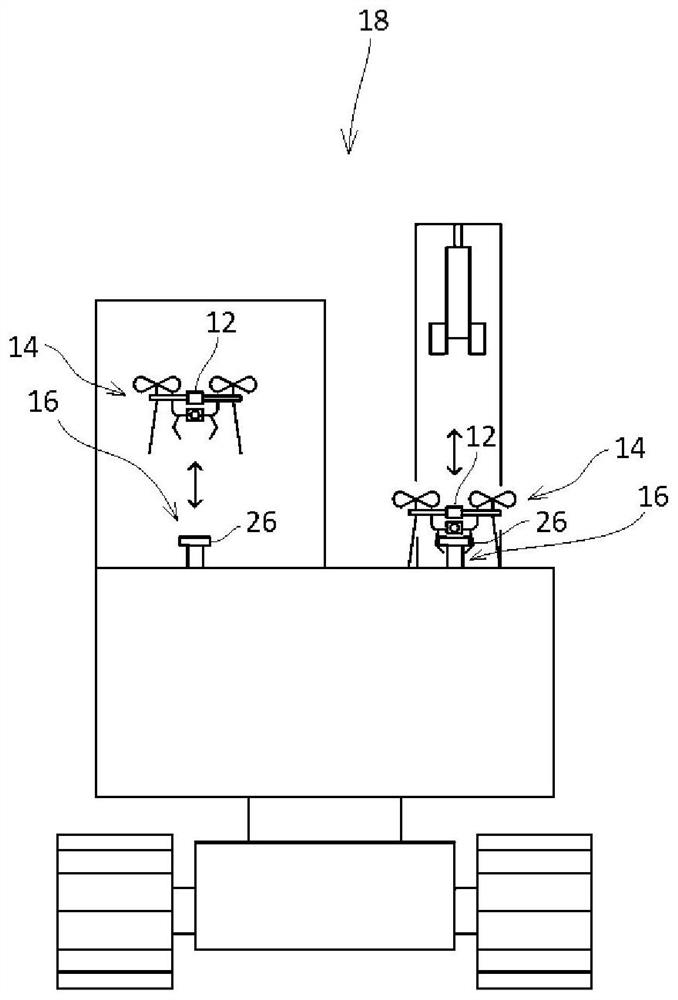
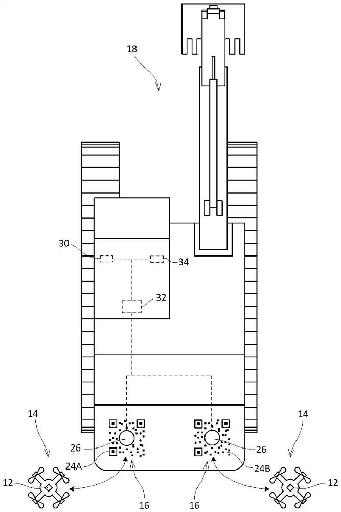
[0026] Such as Figure 1~3 As shown, the operating machine driving system 10 according to the first embodiment of the present invention has an unmanned aerial vehicle 14 equipped with a GNSS receiving unit 12 and operating machines 18 and 20 equipped with a landing port 16, and is configured to The GNSS receiver 12 of the unmanned aerial vehicle 14 of 16 obtains the position information about the work machines 18 and 20 . It should be noted that the location information includes horizontal location information and height information. In a first embodiment, RTK positioning is used as GNSS. The GNSS receiving unit 12 assumes the role of a mobile station for RTK. In addition, a fixed base station 22 for RTK is set at the work site. It should be noted that network RTK may also be used to set a virtual base point instead of setting the fixed base station 22 .

[0027] Work machine 18 is a hydraulic excavator, and work machine 20 is a bulldozer. It should be noted that, in fig...


PUM


Abstract

The present invention reduces the cost of a steering system of a working machine using GNSS. A driving system (10) for a working machine has a drone (14) equipped with a GNSS receiving unit (12) and working machines (18, 20) equipped with a takeoff and landing port (16), and the working machine is configured to The GNSS receiving unit (12) of the drone (14) in the port (16) obtains the position information about the working machine (18, 20).

Description

technical field [0001] The present invention relates to a driving system of working machines such as construction machines and agricultural machines using GNSS. Background technique [0002] In recent years, for working machines such as construction machinery and agricultural machinery, unmanned automatic driving systems using GNSS (Global Navigation Satellite System) such as GPS, GLONASS, and Galileo, and auxiliary operators such as MG (Machine Guidance) and MC (Machine Control) The driving system of the operation is put into practical use (for example, refer to patent document 1). Specifically, the work machine includes an antenna (GNSS receiver) for receiving radio waves transmitted from the artificial satellite, and calculates the distance between the artificial satellite and the antenna based on orbit information and time information of the artificial satellite received via the antenna. The distances between the antenna and a plurality of (four or more, preferably five...

Claims


Application Information

Patent Timeline
Patent Type & Authority Patents(China)
IPC IPC(8): G01C15/00E02F9/20G06V20/17
CPCE02F9/20G01C15/00B64C39/024G05D1/0684G05D2201/0202G05D1/0278G05D1/0027G06V20/176G06V20/10G06V10/245G06V20/17B64U2101/30B64U80/86G05D2201/0201B64U70/00
Inventor 玉里芳直
Owner J THINK CORP
Why Eureka
Try Eureka