Mechanical mold spraying device

A technology of spraying equipment and molds, which is applied to coatings, spray booths, spraying devices, etc., can solve the problems of poor spraying quality, low work efficiency, inconvenient use, etc., and achieve the effect of simple operation, convenient use and convenient use.

Inactive Publication Date: 2020-04-14
谢洁萍
View PDF7 Cites 11 Cited by
  • Summary
  • Abstract
  • Description
  • Claims
  • Application Information

AI Technical Summary

Problems solved by technology

[0004] The purpose of this invention is to solve the shortcomings of the existing spraying equipment, such as low

Method used


Image

  • Mechanical mold spraying device
  • Mechanical mold spraying device
  • Mechanical mold spraying device

Examples


Embodiment 1

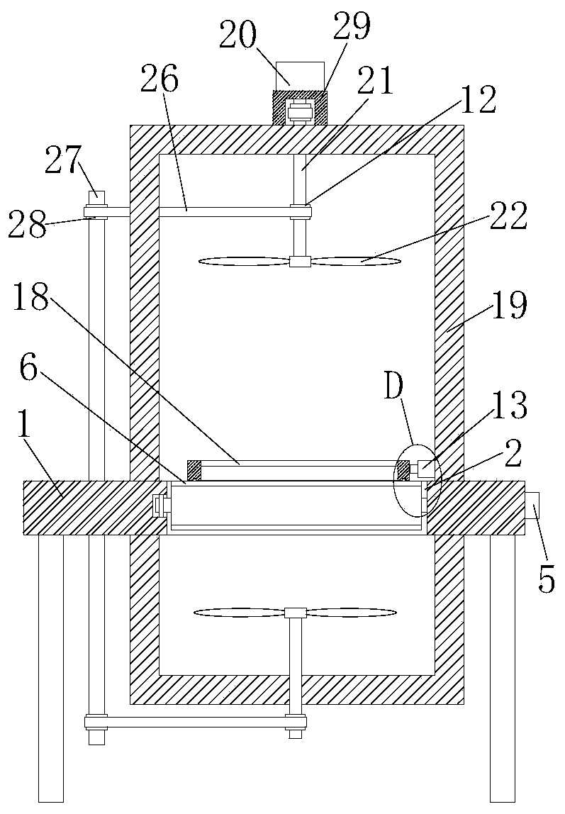
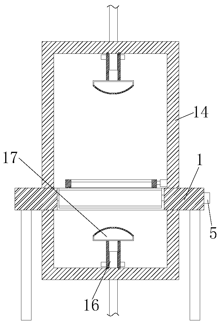
[0030] refer to Figure 1-6 , a kind of mechanical mold spraying equipment, comprising an operation table 1, a transmission hole 2 is opened on one side of the operation table 1, three rotating shafts 3 are rotatably connected to the inner wall of the transmission hole 2, and a first motor is fixedly installed on one side of the operation table 1 5. The output shaft of the first motor 5 is fixedly connected to the corresponding rotating shaft 3. The outer fixed sleeve of the rotating shaft 3 is provided with a transmission wheel 4. The three transmission wheels 4 are connected to two conveyor belts 6, and the two conveyor belts 6 are fixed. A plurality of positioning rods 7 are installed, and the top of the positioning rod 7 is fixedly equipped with two symmetrically arranged fixed rods 8. On the operating table 1, a spraying box 14 and an air-drying box 19 are fixedly installed. On the top inner wall and the bottom inner wall of the spraying box 14 Both are rotatably connecte...

Embodiment 2

[0041] refer to Figure 1-6 , a kind of mechanical mold spraying equipment, comprising an operation table 1, a transmission hole 2 is opened on one side of the operation table 1, three rotating shafts 3 are rotatably connected to the inner wall of the transmission hole 2, and a first motor 5 is welded on one side of the operation table 1 , the output shaft of the first motor 5 is fixedly connected to the corresponding rotating shaft 3, and the outer fixed sleeve of the rotating shaft 3 is provided with a transmission wheel 4, and two transmission belts 6 are connected to the three transmission wheels 4, and two transmission belts 6 are welded between A plurality of positioning rods 7, the top of the positioning rod 7 is welded with two symmetrically arranged fixed rods 8, a spraying box 14 and an air-drying box 19 are welded on the operating table 1, and the top inner wall of the spraying box 14 is connected with the bottom inner wall in rotation. The water guide pipe 16 is rota...


PUM


Abstract

The invention belongs to the field of mold spraying device, and in particular, relates to a mechanical mold spraying device. For the problems that a conventional spraying device is low in working efficiency, poor in spraying quality and inconvenient to use, the following scheme is proposed, the mechanical mold spraying device comprises an operation table; a conveying hole is formed in one side ofthe operation table; three rotating shafts are rotatably connected to the inner wall of the conveying hole; first motors are fixedly mounted on one side of the operation table; output shafts of the first motors are fixedly connected with the corresponding rotating shafts; a conveying wheel fixedly sleeves the outer side of each rotating shaft; two conveying belts are in transmission connection with the three conveying wheels; a plurality of positioning rods are arranged between the two conveying belts, two symmetrically-arranged fixed rods are fixedly arranged at the tops of the positioning rods, a spraying box and an air drying box are fixedly arranged on the operation table, water guide pipes are connected to the inner wall of the top of the spraying box and the inner wall of the bottomof the spraying box, and water inlet pipes are rotatably connected into the water guide pipes. The mechanical mold spraying device is easy to operate and convenient to use, a mold can be sprayed morecomprehensively and conveniently, and people can use the mechanical mold spraying device conveniently.

Description

technical field [0001] The invention relates to the technical field of mold spraying equipment, in particular to a mechanical mold spraying equipment. Background technique [0002] Molds are various molds and tools used in industrial production for injection molding, blow molding, extrusion, die-casting or forging forming, smelting, stamping, etc. to obtain the required products. In short, molds are tools used to make shaped objects , this tool is composed of various parts, and different molds are composed of different parts. It mainly realizes the processing of the shape of the article through the change of the physical state of the formed material, known as the "mother of industry". [0003] After the existing mold is processed and manufactured, it usually needs to be sprayed with paint to protect it and improve its service life. The existing spraying equipment has low working efficiency, poor spraying quality and inconvenient use, so we propose a mechanical mold sprayin...

Claims


Application Information

Patent Timeline
IPC IPC(8): B05B16/20B05B16/00B05B13/02B05B13/04B05D3/04
CPCB05B13/0235B05B13/0421B05D3/0406B05B16/20B05B16/95
Inventor 谢洁萍
Owner 谢洁萍
Why Eureka
Try Eureka