
Self-discharging type stamping and forming all-in-one machine

A technology of stamping forming and integrated machine, which is applied in the direction of metal processing equipment, feeding devices, manufacturing tools, etc., can solve the problems of stamping accidents and low work efficiency, and achieve the effects of avoiding stamping accidents, saving time, and being easy to take

Inactive Publication Date: 2020-04-14
申继州
View PDF6 Cites 33 Cited by
  • Summary
  • Abstract
  • Description
  • Claims
  • Application Information

AI Technical Summary

Problems solved by technology

[0004] In order to overcome the shortcomings of manually putting the workpiece into the punching machine when stamping the workpiece, it is easy to cause stamping accidents, and the work efficiency is low. Time, simple and convenient operation, and self-unloading stamping and forming machine that can avoid stamping accidents

Method used


Image

  • Self-discharging type stamping and forming all-in-one machine
  • Self-discharging type stamping and forming all-in-one machine
  • Self-discharging type stamping and forming all-in-one machine

Examples


Embodiment approach 1

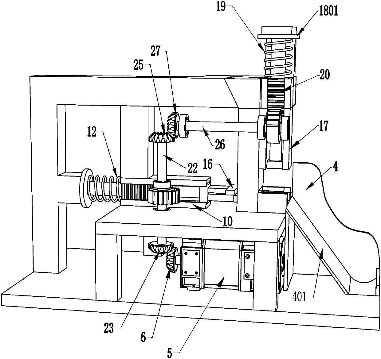
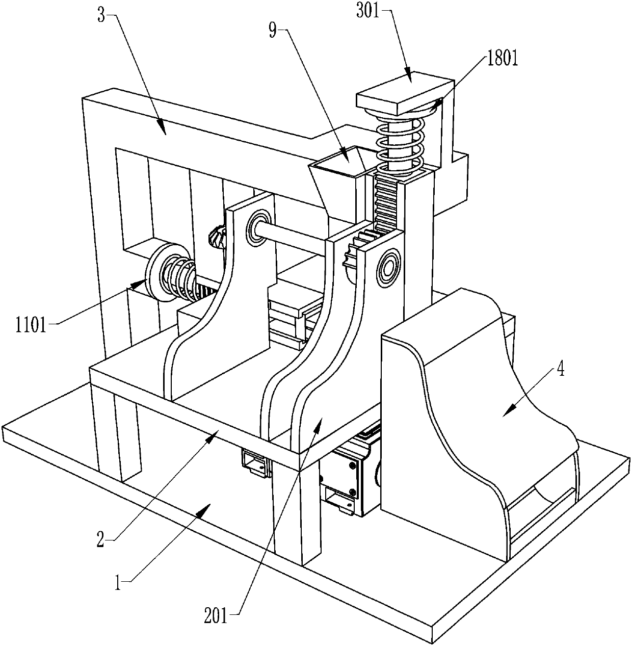
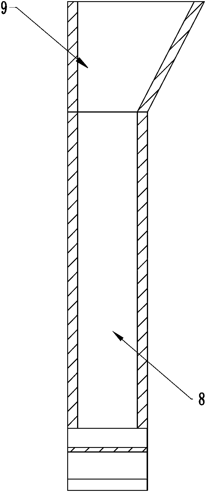
[0020] A self-unloading stamping and forming machine, such as Figure 1-4 As shown, it includes a chassis 1, a frame 2, a curved plate 201, a support column 3, an L-shaped block 301, a motor 5, a stamping frame 7, a discharge frame 8, a storage frame 9, a pushing mechanism and a bending mechanism , the chassis 1 is fixed with a frame 2, a support column 3 and a motor 5, the frame 2 is located on the right side of the support column 3, the motor 5 is located below the frame 2, and three arc-shaped plates 201 are fixedly connected to the top of the frame 2. Frame 2 left middle is fixedly provided with stamping frame 7, is provided with discharge frame 8 on the punch frame 7, and discharge frame 8 is connected with frame 2, and discharge frame 8 top is provided with material storage frame 9, and material storage frame 9 and The support column 3 is connected, and the frame 2 is provided with a pushing mechanism, which is used for unloading. The shape block 301 is provided with a ...

Embodiment approach 2

[0027] On the basis of Embodiment 1, if Figure 1-2 As shown, it also includes a box body 4 and a sloping plate 401 , the box body 4 is arranged on the right side of the top of the chassis 1 , the box body 4 is located on the right side of the frame 2 , and the box body 4 is provided with a sloping plate 401 .

[0028] The box body 4 can collect stamped workpieces, and people don't need to collect them all the time. The inclined plate 401 can effectively allow the workpieces to slide into the receiving box, which is convenient for taking.


PUM


Abstract

The invention relates to a stamping and forming all-in-one machine, in particular to a self-discharging type stamping and forming all-in-one machine. The self-discharging type stamping and forming all-in-one machine can achieve automatic feeding, can continuously work, can save time, is easy and convenient to operate and can also avoid stamping accidents. The self-discharging type stamping and forming all-in-one machine comprises a chassis, a rack, an arc-shaped plate, a supporting column, an L-shaped block, a motor and the like. The rack, the supporting column and the motor are fixedly arranged on the chassis, the rack is located on the right side of the supporting column, and the motor is located below the rack. According to the invention, a stamped workpiece can be pushed out through apushing mechanism, and the other workpiece in a discharging frame can be pushed into a punching frame, so that people can take down the punched workpiece, the workpiece does not need to be placed manually, automatic feeding and continuous work can be achieved, a large amount of time is saved, operation is easy and convenient, and punching accidents can be avoided.

Description

technical field [0001] The invention relates to a stamping and forming integrated machine, in particular to a self-unloading type stamping and forming integrated machine. Background technique [0002] The stamping machine is a stamping press, which is more and more widely used in production. People punch blanks into workpieces with specific shapes. The operation method is to put the workpieces into the stamping one by one by manual or mechanical However, for a large number of workpieces, the efficiency will be very low if the workpieces are put into the stamping machine manually or by a mechanical arm. The distance between the manpower to grasp the metal profile and the stamping machine is very close, which may easily cause stamping accidents. [0003] We have developed a device that can realize automatic feeding, continuous work, save time, is simple and convenient to operate, and can avoid stamping accidents to solve the existing problems. Contents of the invention [0...

Claims


Application Information

Patent Timeline
Patent Type & Authority Applications(China)
IPC IPC(8): B21D43/02B21D43/20B21D45/04
CPCB21D43/027B21D43/20B21D45/04
Inventor 申继州
Owner 申继州
Learn More