Machine tool spindle installation supporting frame
A technology of machine tool spindles and support frames, which is applied to metal processing machinery parts, large fixed members, metal processing equipment, etc., can solve labor-intensive and unsafe problems, and achieve the effects of stable spindle placement, precise and convenient installation, and safe operation
- Summary
- Abstract
- Description
- Claims
- Application Information
AI Technical Summary
Problems solved by technology
Method used
Image

Examples
Embodiment 1
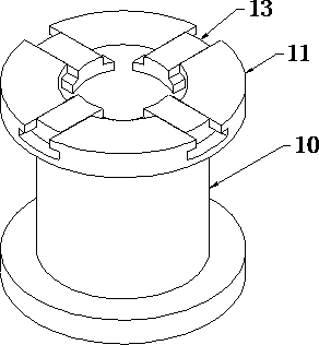
[0016] Such as image 3 As shown, a machine tool spindle installation support frame includes a support frame body 10 , the support frame body 10 is a cylindrical structure with an open top, and the top opening of the support frame body 10 is horizontally turned outward to form a support platform 11 .
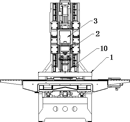
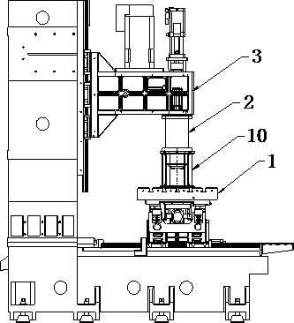
[0017] Such as figure 1 and 2 As shown, when installing the machine tool spindle 2, place the support frame on the workbench 1 of the machine tool, place the tool mounting end of the spindle 2 downwards in the opening of the support frame body 10, and support the platform 11 and the convex ring in the middle of the spindle 2 Contact and support the main shaft 2, so that the main shaft 2 can have a certain installation height on the one hand, so that it can meet the formation requirements of the headstock 3 of the machine tool and realize installation; on the other hand, due to the support structure of the support frame body 10, the The main shaft 2 is suspended in the air to p...
Embodiment 2
[0021] This implementation is improved on the basis of Example 1, and the purpose is to improve the scope of application of the support frame. The difference between this implementation and Example 1 is:
[0022] Such as image 3 As shown, the support platform 11 is provided with an adjustment plate 13 that slides along the radial direction of the support frame body 10, the adjustment plate 13 is arranged along the radial direction of the support frame body 10, and the top surface of the adjustment plate 13 is in contact with the The support platform 11 is level.
[0023] Different machine tools will correspond to different main shafts 2. When the main shaft 2 is so thin that the support platform 11 cannot support the main shaft 2, the adjustment plate 13 can be slid to the top opening of the support frame body 10 so that the main shaft 2 can be placed on the adjustment plate 13. The work of installing the main shaft can be completed by utilizing the support frame of the pres...
Embodiment 3
[0026] In order to improve the convenience of the installation and alignment of the main shaft 2 and the main shaft box 3, the support frame body 10 should have the function of height adjustment. This implementation is improved on the basis of Examples 1 and 2, and the purpose is to provide a support frame The height adjustment function, its main features are:
[0027] Such as Figure 4 As shown, an adjustment device is provided at the bottom of the support frame body 10. The adjustment device includes a base 21. At least one screw 22 is arranged on the top of the base 21. The bottom of the screw rod 22 is rotatably arranged in the base 21. The support frame body 10 A nut 23 cooperating with the screw rod 22 is fixedly installed on the side wall.
[0028] When the screw rod 22 is turned like this, the characteristics of the thread will drive the support frame body 10 to move up and down, so as to realize the fine adjustment of the support frame body 10. When the spindle box 3...
PUM
 Abstract
Description
Claims
Application Information
 - R&D
- Intellectual Property
- Life Sciences
- Materials
- Tech Scout
- Unparalleled Data Quality
- Higher Quality Content
- 60% Fewer Hallucinations
Browse by: Latest US Patents, China's latest patents, Technical Efficacy Thesaurus, Application Domain, Technology Topic, Popular Technical Reports.
© 2025 PatSnap. All rights reserved.Legal|Privacy policy|Modern Slavery Act Transparency Statement|Sitemap|About US| Contact US: help@patsnap.com