

Machining aluminum plate cutting device
A cutting device and mechanical processing technology, applied in the direction of shearing devices, metal processing equipment, shearing machine accessories, etc., can solve the problems of poor adjustability and inability to realize efficient cutting of aluminum plates, and achieve the goal of ensuring smooth cutting and smooth cutting Effect
- Summary
- Abstract
- Description
- Claims
- Application Information
AI Technical Summary
Problems solved by technology
Method used
Image

Examples
Embodiment 1
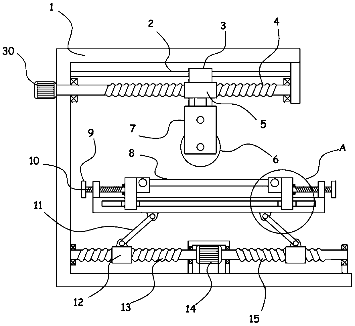
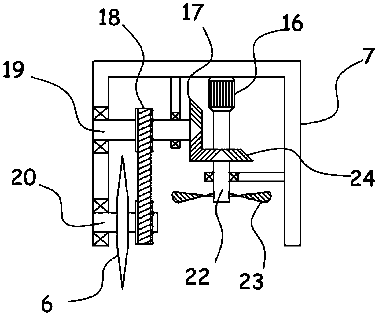
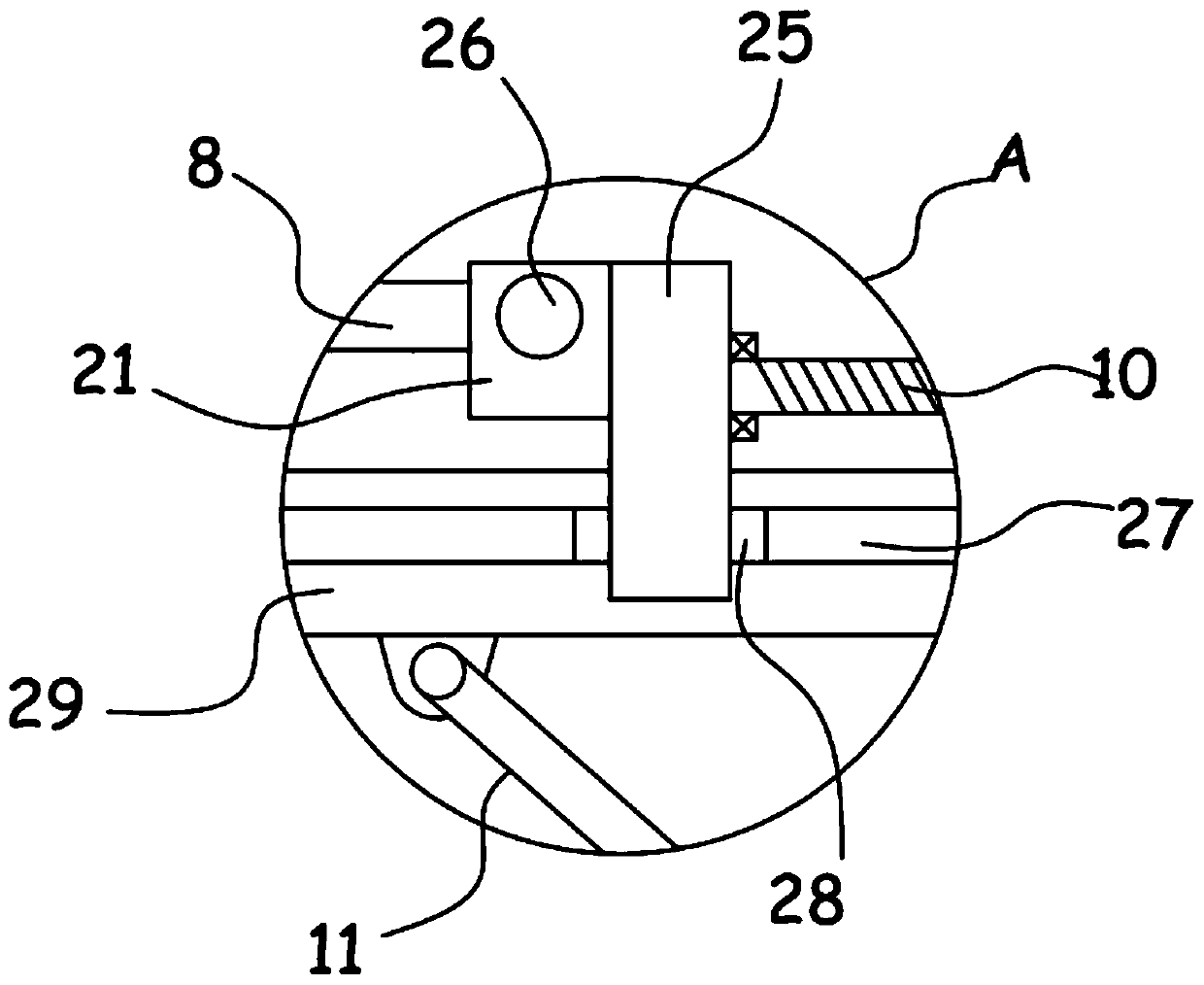
[0025] see Figure 1-4 , a machined aluminum plate cutting device, comprising a support frame 1, a motor II30 is fixed on the support frame 1, the motor II30 is driven and connected with a translation mechanism, the translation mechanism is connected with a hanger 7, and the hanger 7 is provided with a blade 6. The cutting mechanism in the cutting mechanism is connected with a blowing mechanism, and the support frame 1 is connected with a horizontal lifting frame 29 through a lifting mechanism, and a pair of sliding frames 25 are slidably installed on the lifting frame 29. There is a locking mechanism for adjusting the lateral movement of the sliding frame 25 relative to the elevating frame 29 , and the sliding frame 25 is provided with an adjusting mechanism for adjusting the longitudinal movement of the aluminum plate 8 .
[0026] The locking mechanism provided in the device can drive the sliding frame 25 to lock and fix the aluminum plate 8 laterally, and the horizontal mov...
Embodiment 2
[0031] On the basis of Embodiment 1, in addition, the lifting mechanism includes a biaxial motor 14, and two output shafts of the biaxial motor 14 are coaxially fixed with a screw mandrel I13 and a screw mandrel II15 respectively, and the screw mandrel I13 and the screw mandrel II15 are threaded A screw mandrel cover block 12 is sleeved, and a support rod 11 is hinged between the screw mandrel cover block 12 and the lifting frame 29, and the helical directions of the screw mandrel I13 and the screw mandrel II15 are opposite.
[0032] The double-axis motor 14 can simultaneously drive the screw mandrel I13 and the screw mandrel II15 to rotate, and the screw mandrel I13 and the screw mandrel II15 drive the two screw mandrel sets 12 to move toward or away from each other, and then the support rod 11 drives the lifting frame 29 to realize height adjustment , so that the aluminum plate 8 on the lifting frame 29 can be fully penetrated and cut by the blade 6 .
[0033] In addition, t...
PUM
 Abstract
Description
Claims
Application Information