
Polishing and deburring device for side wall of metal short pipe

A short tube and metal technology, which is applied in the field of metal short tube side wall grinding and deburring devices, can solve the problems of low grinding efficiency, achieve high-efficiency dust removal, and environmental protection in the deburring process

Inactive Publication Date: 2020-04-14
武文家
View PDF11 Cites 17 Cited by
  • Summary
  • Abstract
  • Description
  • Claims
  • Application Information

AI Technical Summary

Problems solved by technology

The rust removal device for the inner wall of the water conservancy pipeline, through the use of the positioning device and the rust removal device, can firstly locate the steel pipe body conveniently, and then quickly complete the rust removal of the inner wall of the pipe, and can adapt to the rust removal of pipes with different sizes and inner diameters. Although the device can derust the inner wall of the pipe, the grinding efficiency is low, and the inner wall cannot be fully and efficiently deburred. Therefore, a short metal pipe side wall grinding and deburring device is now provided to solve the problem. The above technical issues

Method used


Image

  • Polishing and deburring device for side wall of metal short pipe
  • Polishing and deburring device for side wall of metal short pipe
  • Polishing and deburring device for side wall of metal short pipe

Examples


Embodiment 1

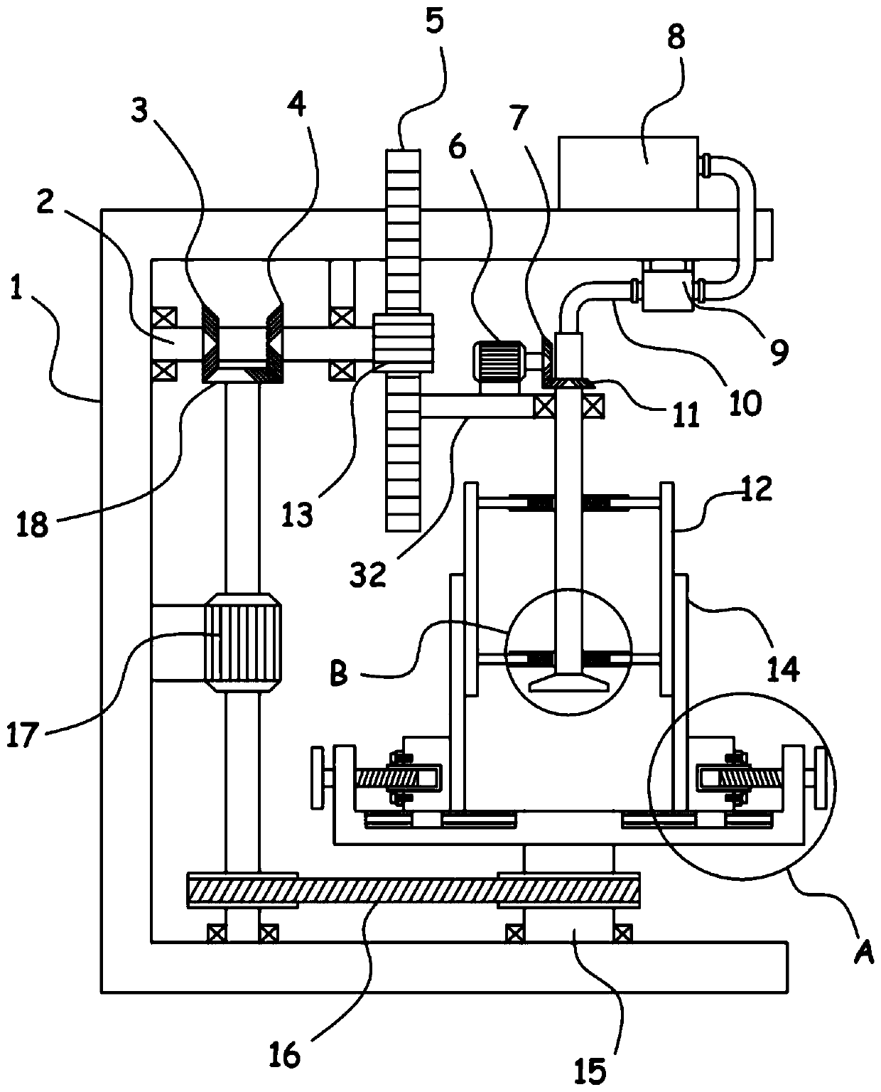
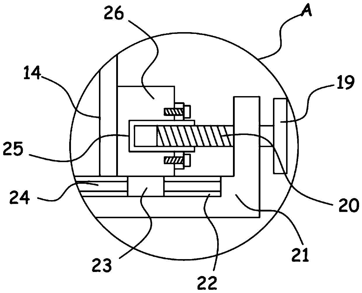
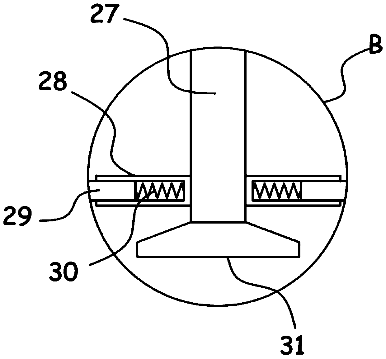
[0025] see Figure 1-4 , a metal short pipe side wall grinding and deburring device, comprising a support frame 1, a rotating shaft 15 is installed on the support frame 1, a support frame 21 is coaxially fixed on the upper end of the rotating shaft 15, and a support frame 21 is provided on the support frame 21 for metal The short tube 14 clamps a fixed clamping mechanism, and the support frame 1 is driven and connected with a horizontal plate 32 arranged horizontally through a lifting mechanism, and a servo motor 6 is fixed on the horizontal plate 32, and the servo motor 6 is driven and connected with a The grinding slat 12 attached to the inner wall of the metal short pipe 14, the top of the support frame 1 is fixed with a dust collection box 8, and the short metal pipe 14 is provided with a dust suction mechanism communicating with the dust collection box 8.

[0026] The device supports the metal short pipe 14 through the supporting frame 21 provided, and the clamping mechan...

Embodiment 2

[0032] On the basis of Embodiment 1, in addition, the elevating mechanism includes a straight toothed rack 5 fixed vertically with the horizontal plate 32, a transmission gear 13 is meshed and connected to the straight toothed rack 5, and a driven gear 13 is coaxially fixed on the transmission gear 13. Axis 2, a biaxial motor 17 is fixed on the support frame 1, an output shaft of the biaxial motor 17 is coaxially fixed with an incomplete bevel gear 18, and the incomplete bevel gear 18 is alternately meshed and connected with a sleeve fixed on the driven shaft 2 The driven bevel gear I3 and the driven bevel gear II4.

[0033] The double-axis motor 17 can drive the rotation of the incomplete bevel gear 18, and the incomplete bevel gear 18 is alternately meshed with the driven bevel gear I3 and the driven bevel gear II4, so that the driven shaft 2 can drive the transmission gear 13 to perform forward and reverse alternately. , and then realized that the straight rack 5 drives the...


PUM


Abstract

The invention discloses a polishing and deburring device for a side wall of a metal short pipe and relates to the technical field of machining. The device comprises a supporting frame, wherein a rotating shaft is rotationally installed on the supporting frame, the supporting frame is coaxially fixed to an upper end of the rotating shaft, a clamping mechanism used for clamping and fixing a metal short pipe is arranged on the supporting frame, a dust collection box is fixed to the top of the supporting frame, and a dust suction mechanism communicated with the dust collection box is arranged in the metal short pipe. The device is advantaged in that the arranged clamping mechanism is used for stably clamping and fixing the metal short pipe, the arranged lifting mechanism can drive a rotating polishing strip plate to do vertical reciprocating motion, the full deburring effect on different vertical height position areas of an inner wall of the metal short pipe is achieved, the arranged rotating shaft can drive the supporting frame to rotate, the supporting frame drives the metal short pipe on the supporting frame to rotate, deburring efficiency of the inner wall of the metal short pipe is greatly improved, dust generated in the polishing and deburring process can achieve the efficient dedusting effect through a dust suction mechanism, and the deburring process is more environmentallyfriendly.

Description

technical field [0001] The invention relates to the technical field of mechanical processing, in particular to a device for grinding and deburring the side wall of a short metal tube. Background technique [0002] Machining refers to the process of changing the shape, size or performance of a workpiece through a mechanical device. In the production process, any process of changing the shape, size, position and nature of the production object to make it a finished or semi-finished product is called crafting process. It is the main part of the production process, and the process can be divided into casting, forging, stamping, welding, machining, assembly and other processes. The mechanical manufacturing process generally refers to the machining process of parts and the assembly process of machines. The other processes are called auxiliary processes, such as transportation, storage, power supply, equipment maintenance, etc. [0003] Authorized announcement number is that the ...

Claims


Application Information

Patent Timeline
IPC IPC(8): B24B9/04B24B41/06B24B47/12B24B55/06
CPCB24B9/04B24B41/06B24B47/12B24B55/06
Inventor 武文家
Owner 武文家
Features
  • Generate Ideas
  • Intellectual Property
  • Life Sciences
  • Materials
  • Tech Scout
  • Unparalleled Data Quality
  • Higher Quality Content
  • 60% Fewer Hallucinations
Learn More