Convenient-to-use cable rack for cable laying

A cable laying and cable rack technology, applied in the field of cable racks, can solve problems such as low work efficiency and troublesome operation, and achieve the effect of improving work efficiency and simple operation

Active Publication Date: 2020-04-14
SHANGHAI MUNICIPAL ELECTRIC POWER CO
View PDF14 Cites 0 Cited by
  • Summary
  • Abstract
  • Description
  • Claims
  • Application Information

AI Technical Summary

Problems solved by technology

[0003] During the cable laying operation, the cable reel needs to be supported by the cable rack, and then the cable can be easily rolled up. However, it is often necessary to use various equipment, tools, and multiple people to erect the cable reel on the cable rack. On the cable rack, the operation is troublesome and the work efficiency is low

Method used


Image

  • Convenient-to-use cable rack for cable laying
  • Convenient-to-use cable rack for cable laying
  • Convenient-to-use cable rack for cable laying

Examples


Embodiment 1

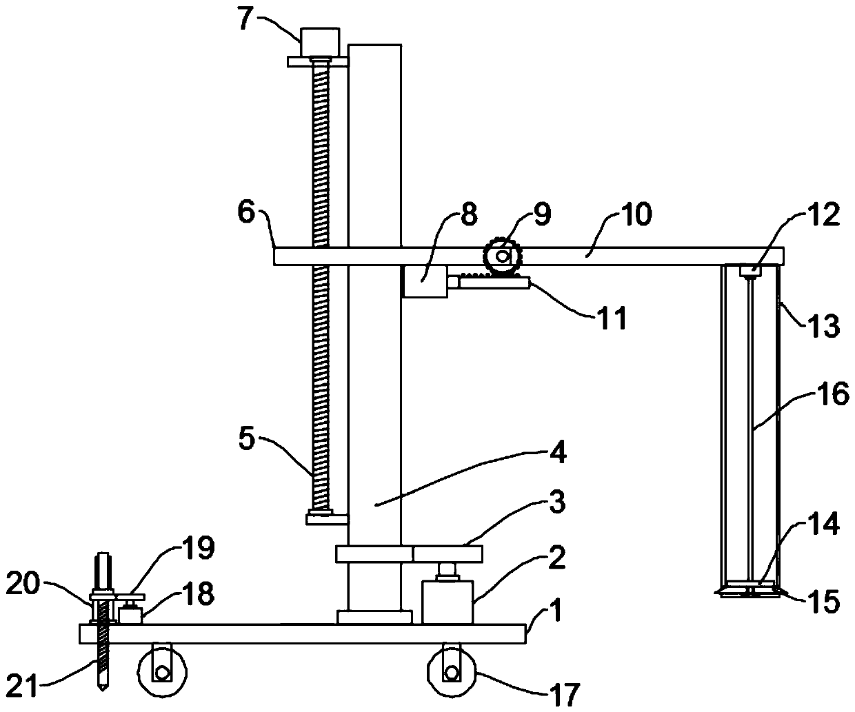
[0024] see Figure 1~2 , in an embodiment of the present invention, a cable rack that is convenient to use for laying cables includes a base plate 1, a mounting column 4 mounted on the base plate 1, and a support unit installed on the mounting column 4 for supporting the cable tray, the base plate 1. Rollers 17 are evenly and symmetrically fixed on the bottom, and the rollers 17 are self-locking rollers, which facilitate the movement of the device. A fixing mechanism for connecting and fixing with the ground is installed on the bottom plate 1. The fixing mechanism includes a second motor 18, The second gear pair 19, the drive sleeve 20 and the threaded drill rod 21, the upper surface of the base plate 1 is rotatably mounted with the drive sleeve 20, the drive sleeve 20 is pierced with a threaded drill rod 21, and the threaded drill rod 21 runs through the base plate 1 and extend to the bottom of the base plate 1, the threaded drill rod 21 is threadedly connected with the base ...

Embodiment 2

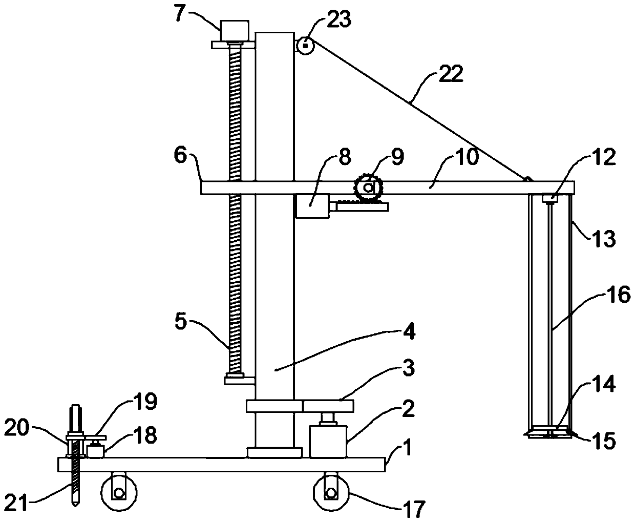
[0027] see image 3The difference between this embodiment of the present invention and Embodiment 1 is that, in order to ensure the safety and stability when adjusting the working angle of the cable reel through the adjustment mechanism, a hoist 23 is fixedly installed on the top of the installation column 4, and a hoist 23 is fixed on the top of the hoist 23. A traction rope 22 is coiled, and the other end of the traction rope 22 is tied to the end of the mounting plate 10, and the winch 23 cooperates with the adjustment mechanism to improve stability.

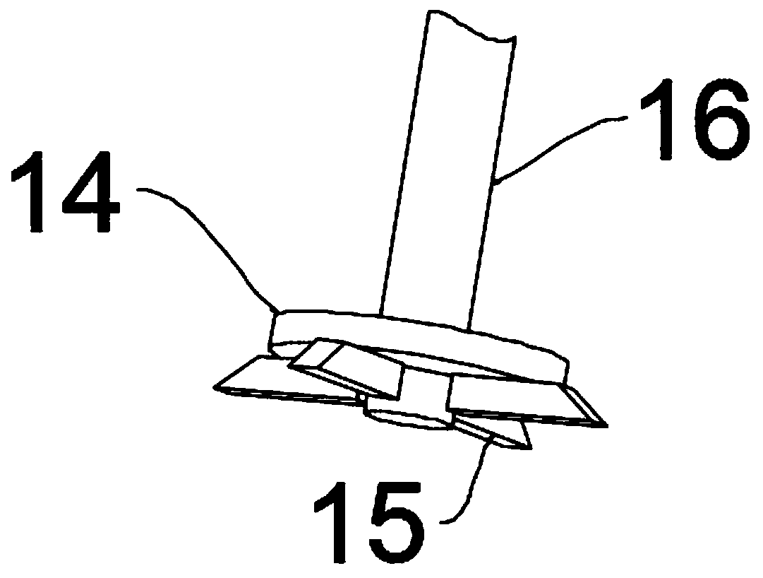
[0028] The working principle of the present invention is: when working, at first, move the device to the side of the cable reel, fix the device through the fixing mechanism, and then drive the supporting column 13 into the middle hole of the cable reel until the supporting column is driven by the lifting mechanism. 13 moves to the bottom of the cable reel, and then starts the fourth motor 12, the fourth motor 12 drives the ro...


PUM


Abstract

The invention discloses a convenient-to-use cable rack for cable laying. The cable rack comprises a bottom plate, a mounting column mounted on the bottom plate, and a supporting unit mounted on the mounting column and used for supporting a cable reel. The supporting unit comprises a supporting assembly and a lifting mechanism used for driving the supporting assembly to ascend and descend. The supporting assembly comprises a supporting plate and a supporting column which is fixedly installed on the supporting plate and used for supporting the cable reel. A rotating shaft is rotationally mountedin an inner cavity of the supporting column; a rotating disc is fixed to the bottom of the rotating shaft; a plurality of extension rods for supporting the cable reel are annularly arranged at the bottom of the inner cavity of the supporting column and located on the lower surface of the rotating disc; the upper surface of each extension rod is connected with the lower surface of the rotating disc through a plane thread; the supporting plate is formed by rotationally connecting a movable plate and an installation plate; and an adjusting mechanism used for adjusting the angle of the installation plate is connected between the movable plate and the installation plate. Through arrangement of the supporting unit, the cable rack is convenient and practical, and work can be done by one person;and through arrangement of an adjusting mechanism, the working angles of the mounting plate and the supporting column on the mounting plate can be adjusted.

Description

technical field [0001] The invention relates to the technical field of cable laying equipment, in particular to a convenient cable rack for cable laying. Background technique [0002] Cable laying refers to the process of laying and installing cables along the surveyed route to form a cable route. According to the application occasion, it can be divided into several laying methods such as overhead, underground (pipeline and direct burial), underwater, wall and tunnel. Reasonable selection of cable laying method is very important to ensure the transmission quality, reliability and construction maintenance of the line. [0003] During the cable laying operation, the cable reel needs to be supported by the cable rack, and then the cable can be easily rolled up. However, it is often necessary to use various equipment, tools, and multiple people to erect the cable reel on the cable rack. On the cable rack, the operation is troublesome and the work efficiency is low. Contents ...

Claims


Application Information

Patent Timeline
IPC IPC(8): B65H54/54B65H54/70
CPCB65H54/54B65H54/70
Inventor 何伟
Owner SHANGHAI MUNICIPAL ELECTRIC POWER CO
Why Eureka
Try Eureka