Gas device and gas leakage detection method thereof
A technology of gas leakage and detection method, which is applied in the testing of mechanical equipment, fluid tightness, and testing of machine/structural components, etc., can solve problems such as easy occurrence of danger, failure to detect gas leakage in time, and avoid safety accidents. Effect
- Summary
- Abstract
- Description
- Claims
- Application Information
AI Technical Summary
Problems solved by technology
Method used
Image


Examples
Embodiment 1
[0033] During the use of gas equipment, the connection between the gas valve and the indoor gas pipeline is not in place, and gas leakage will occur; the aging of the internal connection seal of the whole machine will also cause gas leakage. In the prior art, a gas detection device installed outside the gas equipment is usually used for detection. When the gas equipment is placed in a large space, the leakage of gas cannot be detected in time, which may easily lead to safety accidents. In order to solve the above problems, this embodiment provides a gas leakage detection method for gas equipment. The gas pipeline assembly is provided in the gas equipment, and the gas pipeline assembly is connected to the gas main pipe outside the gas equipment. The gas supply pipeline for the gas supply of multiple gas equipment.
[0034] The gas equipment also includes a gas leakage detection device, which includes a first detection device for detecting the pressure or flow in the gas main pi...
Embodiment 2
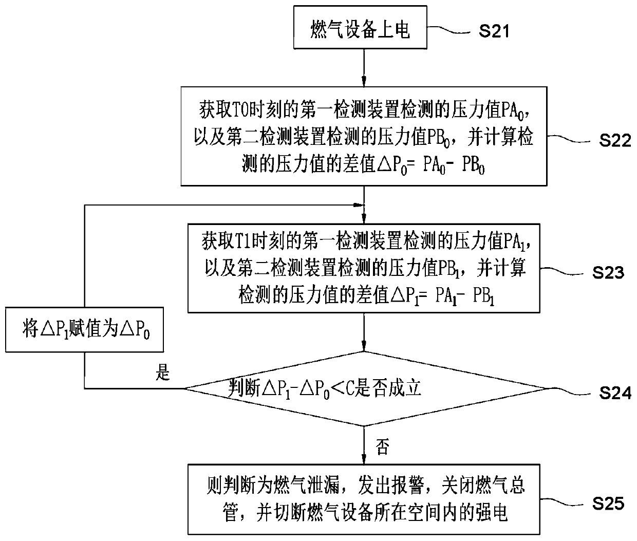
[0041] This embodiment provides a gas leakage detection method for gas equipment, which is an improvement made on the basis of Embodiment 1. This embodiment uses the detection of gas pressure by the first detection device and the second detection device as an example for illustration. At this time, both the first detection device and the second detection device include pressure sensors.
[0042] The gas pipeline assembly includes a gas valve and a gas pipeline. One end of the gas pipeline is connected to the gas valve through a quick joint, and the other end of the gas pipeline is connected to the gas main pipe. In this embodiment, the first detection device is arranged between the gas main pipe and the gas pipeline or It is arranged in the main gas pipe, and the second detection device is arranged between the quick joint and the gas valve. Such as figure 2 As shown, the gas leakage detection method includes the following steps:
[0043] S21, the gas equipment is powered on...
Embodiment 3
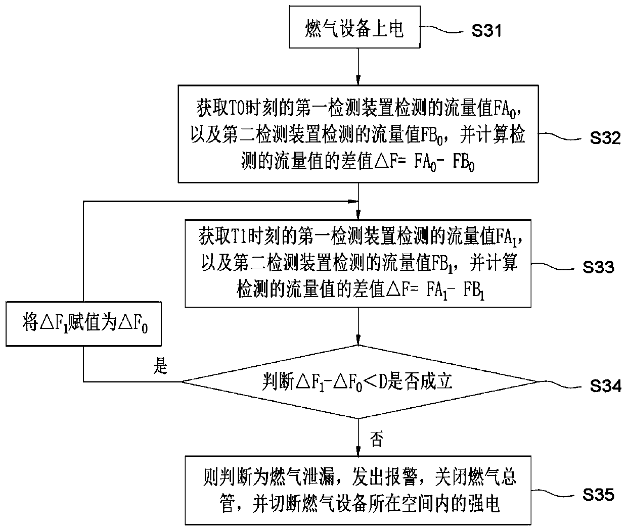
[0051] This embodiment provides a gas leakage detection method for gas equipment, which is an improvement made on the basis of Embodiment 1. This embodiment uses the detection of gas flow by the first detection device and the second detection device as an example for illustration. At this time, both the first detection device and the second detection device include flow sensors. Such as image 3 As shown, the gas leakage detection method includes the following steps:
[0052] S31, the clothes drying equipment is powered on.
[0053] S32. Obtain the flow value FA detected by the first detection device at time T0 0 , and the flow value FB detected by the second detection device 0 , and calculate the difference △F of the detected flow values 0 =FA 0 -FB 0 .
[0054] S33. Obtain the flow value FA detected by the first detection device at time T1 1 , and the flow value FB detected by the second detection device 1 , and calculate the difference △F of the detected flow value...
PUM
 Abstract
Description
Claims
Application Information
 - R&D
- Intellectual Property
- Life Sciences
- Materials
- Tech Scout
- Unparalleled Data Quality
- Higher Quality Content
- 60% Fewer Hallucinations
Browse by: Latest US Patents, China's latest patents, Technical Efficacy Thesaurus, Application Domain, Technology Topic, Popular Technical Reports.
© 2025 PatSnap. All rights reserved.Legal|Privacy policy|Modern Slavery Act Transparency Statement|Sitemap|About US| Contact US: help@patsnap.com