
Platform door and signal interface state monitoring device

A technology of condition monitoring device and signal interface, applied in program control, instrument, computer control, etc., can solve the problems of limited maintenance processing time, short duration of failure, and great influence on normal operation of subway, and achieve auxiliary fault analysis and judgment, The effect of reducing maintenance processing time and low cost of technical transformation

Pending Publication Date: 2020-04-14
OPERATION BRANCH OF SHENYANG METRO CO LTD
View PDF10 Cites 6 Cited by
  • Summary
  • Abstract
  • Description
  • Claims
  • Application Information

AI Technical Summary

Problems solved by technology

[0002] The failure of the interface between the platform door system and the signal system directly causes the train and the platform door to be unable to be linked or there is no fully closed signal, which affects the traffic order and has a greater impact on the fault; and such failures involve the platform door system and the signal system, fault analysis and judgment Difficulty; at the same time, during normal operation, the actual allowable repair processing time is very limited
[0003] At present, the interface between the existing platform equipment and signal equipment is only a terminal block. When a fault occurs between the platform door and the signal interface, because it involves the platform door system and the signal system, the fault lasts for a short time and recovers instantaneously. It occurs frequently, and it is difficult to analyze and judge the fault. Large, it is not convenient for troubleshooting and troubleshooting. After the fault occurs, it will have a great impact on the normal operation of the subway

Method used


Image

  • Platform door and signal interface state monitoring device
  • Platform door and signal interface state monitoring device
  • Platform door and signal interface state monitoring device

Examples


Embodiment Construction

[0019] The specific implementation manners of the present invention will be further described in detail below in conjunction with the accompanying drawings and embodiments. The following examples are used to illustrate the present invention, but are not intended to limit the scope of the present invention.

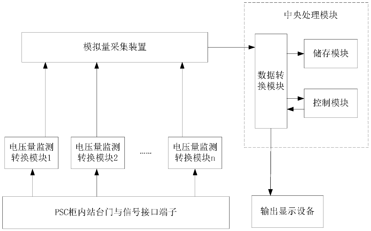
[0020] like figure 1 As shown, the method of this embodiment is as follows.

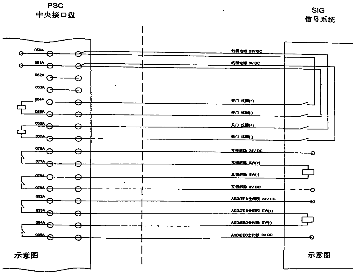
[0021] The invention provides a platform door and signal interface state monitoring device, comprising a PSD system (rail transit platform screen door system Platform Screen Doors system for short PSD system) platform door equipment side and a SIG system (signal system Signalsystem for short SIG system) signal equipment side, PSC is the central interface panel, which is equipped with uplink and downlink platform door logic control unit (PEDC), main monitoring system (MMS) and platform door system wiring terminals and relays, such as figure 2 The schematic diagram of the terminal connection bet...


PUM


Abstract

The invention, which relates to the technical field of electrician preparation and application, provides a platform door and signal interface state monitoring device. The device comprises a voltage quantity monitoring conversion module, an analog quantity acquisition device, a central processing module and output display equipment. The input terminal of the voltage quantity monitoring conversion module is connected with interfaces of platform door side and signal side equipment, and the output terminal of the voltage quantity monitoring conversion module is connected with the input terminal ofthe analog quantity acquisition device; the analog quantity acquisition device is connected with the central processing module; and the output terminal of the central processing module is connected with the input terminal of output display equipment. The device monitors and analyzes the state signals of the platform door and the signal interface in real time, so that when a fault occurs, the fault reason and the fault position can be visually displayed at the first time; and thus the maintenance personnel can conveniently and quickly maintain and process the fault, so that the troubleshootingprocessing time is greatly shortened.

Description

technical field [0001] The invention relates to the technical field of electrical preparation and application, in particular to a state monitoring device for a platform door and a signal interface. Background technique [0002] The failure of the interface between the platform door system and the signal system directly causes the train and the platform door to be unable to be linked or there is no fully closed signal, which affects the traffic order and has a greater impact on the fault; and such failures involve the platform door system and the signal system, fault analysis and judgment Difficulty; at the same time, during normal operation, the actual allowable repair processing time is very limited. [0003] At present, the interface between the existing platform equipment and signal equipment is only a terminal block. When a fault occurs between the platform door and the signal interface, because it involves the platform door system and the signal system, the fault lasts ...

Claims


Application Information

Patent Timeline
Patent Type & Authority Applications(China)
IPC IPC(8): G05B19/042
CPCG05B19/0428G05B2219/24024
Inventor 吴李刚桂思平黄玉涛解明东孙红印许永欣刚红雨李恒任鹏孙磊刘东洋边泳光范静丰李末赵凯侯恩博何维黄树智胡洋李罡李爱华杨宁赵海军耿明程子健张兵
Owner OPERATION BRANCH OF SHENYANG METRO CO LTD
Learn More