
Signal transceiver with angle adjusting function based on remote sensing technology

A signal transceiver and angle adjustment technology, applied in the direction of reflection/re-radiation and utilization of re-radiation of instruments, radio waves, etc., can solve the problems of poor contact, inaccurate signal reception, inconvenient use by users, etc., and prolong the service life. ,Easy to maintain and deal with and reduce the effect of damage

Pending Publication Date: 2020-10-30
湖南星图空间信息技术有限公司
View PDF6 Cites 0 Cited by
  • Summary
  • Abstract
  • Description
  • Claims
  • Application Information

AI Technical Summary

Problems solved by technology

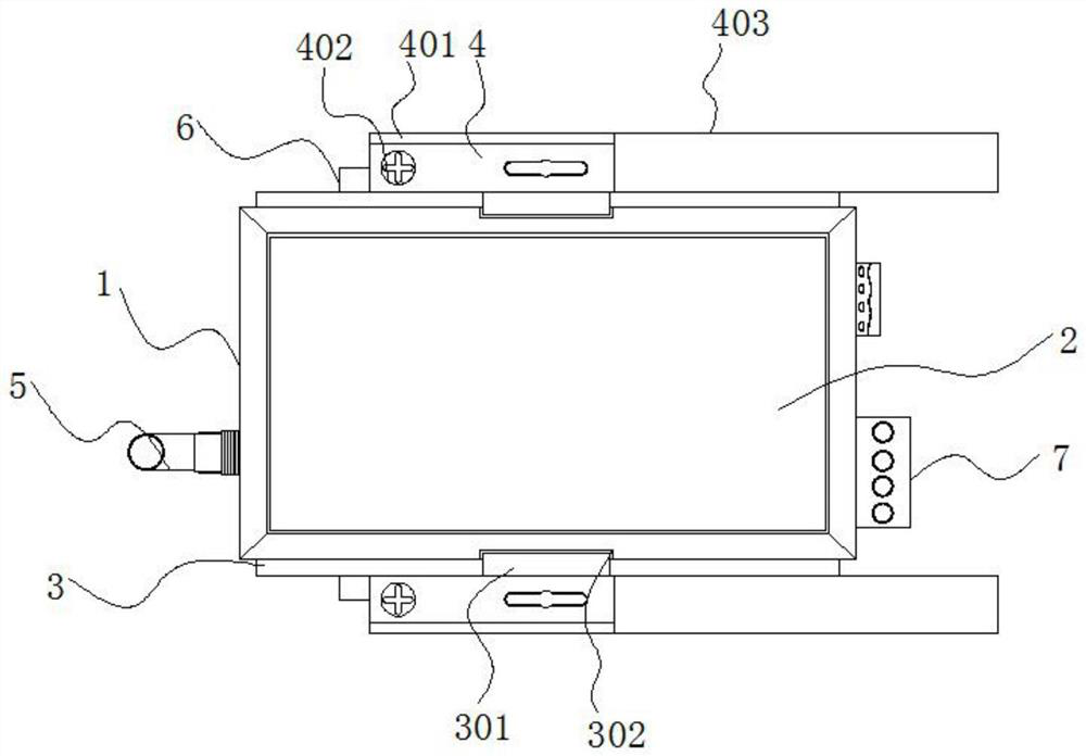
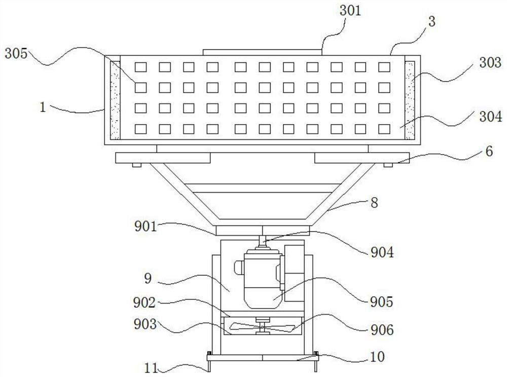
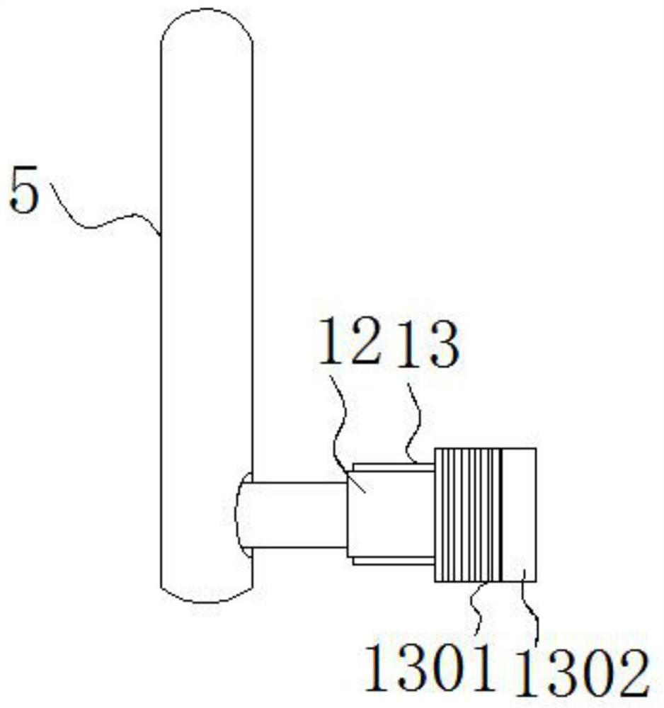
[0004] The purpose of the present invention is to provide a signal transceiver with an angle adjustment function based on remote sensing technology, so as to solve the problem that the signal transceiver proposed in the above background technology is inconvenient for the user to protect the connection between the transceiver rod and the main body during use, resulting in Poor contact will occur during use, which will bring inconvenience to the user, and it will be inconvenient for the user to flexibly adjust the placement angle of the signal transceiver according to the actual use needs during use, resulting in Insufficient precision, poor heat dissipation, and poor protection for signal transceivers

Method used


Image

  • Signal transceiver with angle adjusting function based on remote sensing technology
  • Signal transceiver with angle adjusting function based on remote sensing technology
  • Signal transceiver with angle adjusting function based on remote sensing technology

Examples


Embodiment Construction

[0026] The following will clearly and completely describe the technical solutions in the embodiments of the present invention with reference to the accompanying drawings in the embodiments of the present invention. Obviously, the described embodiments are only some, not all, embodiments of the present invention. Based on the embodiments of the present invention, all other embodiments obtained by persons of ordinary skill in the art without making creative efforts belong to the protection scope of the present invention.

[0027] In the description of the present invention, unless otherwise stated, the meaning of "plurality" is two or more; the terms "upper", "lower", "left", "right", "inner", "outer" , "front end", "rear end", "head", "tail", etc. indicate the orientation or positional relationship based on the orientation or positional relationship shown in the drawings, and are only for the convenience of describing the present invention and simplifying the description, rather...


PUM


Abstract

The invention discloses a signal transceiver with an angle adjusting function based on a remote sensing technology, and relates to the technical field of signal transceivers. The signal transceiver comprises a main body and a fixing bolt, wherein a protection device is arranged in the main body, heat dissipation devices are arranged at two ends of the outer portion of the main body, auxiliary devices are arranged at one ends of the outer portions of the bottoms of the heat dissipation devices, and bottom plates are arranged at one ends of the outer portions of the bottoms of the auxiliary devices. According to the invention, a buffer cavity is arranged, is made of rubber and is internally hollow, so that a user can fill gas into the buffer cavity in advance according to specific protectionrequirements, when the signal transceiver is under the action of a large force, the force can be buffered by utilizing the wriggling of the gas in the buffer cavity, the signal transceiver can be further protected, and the service life of the signal transceiver can be effectively prolonged to a certain extent; and the buffer cavity can be selectively mounted and dismounted according to the use requirements, the structure is simple, and the use of a user is facilitated.

Description

technical field [0001] The invention relates to the technical field of signal transceivers, in particular to a signal transceiver with an angle adjustment function based on remote sensing technology. Background technique [0002] A signal generator, also known as a signal source or an oscillator, is a device that can provide electrical signals of various frequencies, waveforms, and output levels. It is used as a test signal source or excitation source when measuring the amplitude characteristics, frequency characteristics, transmission characteristics and other electrical parameters of various telecommunication systems or telecommunication equipment, as well as when measuring the characteristics and parameters of components. [0003] The signal transceivers on the market are inconvenient for users to protect the connection between the transceiver rod and the main body during use, resulting in poor contact during use, which brings inconvenience to users and is inconvenient to...

Claims


Application Information

Patent Timeline
Patent Type & Authority Applications(China)
IPC IPC(8): G01S7/02G01S13/89G01C11/02
CPCG01S7/02G01S13/89G01C11/02
Inventor 张佳栋匡澍张华廖晓航罗青青任超
Owner 湖南星图空间信息技术有限公司
Learn More