
A sub-format automatic electrical control cabinet with flame retardant and fire-extinguishing function

A technology of electrical control cabinets and formats, applied to housings with display/control units, electrical equipment housings/cabinets/drawers, electrical components, etc., can solve problems such as rapid combustion, loss, and aging of electrical components in control cabinets, and achieve Good flame retardant effect, low production cost and low use cost

Active Publication Date: 2021-04-02
广东盛银新能源科技有限公司
View PDF19 Cites 0 Cited by
  • Summary
  • Abstract
  • Description
  • Claims
  • Application Information

AI Technical Summary

Problems solved by technology

The control cabinet is a power supply device used to provide power for power equipment. During the working process, its internal electronic components will generate a lot of heat. The traditional heat dissipation method uses vents or cooling fans, which has a slow heat dissipation speed and cannot dissipate heat in a timely manner. Excluded, resulting in low operating efficiency of components, which will lead to aging of electrical components in the long run, and even cause electrical components to catch fire; after the electrical components catch fire, it will cause rapid combustion of the entire control cabinet, and it is too late to wait for the staff to fight the fire, resulting in huge loss

Method used


Image

  • A sub-format automatic electrical control cabinet with flame retardant and fire-extinguishing function
  • A sub-format automatic electrical control cabinet with flame retardant and fire-extinguishing function
  • A sub-format automatic electrical control cabinet with flame retardant and fire-extinguishing function

Examples


Embodiment approach

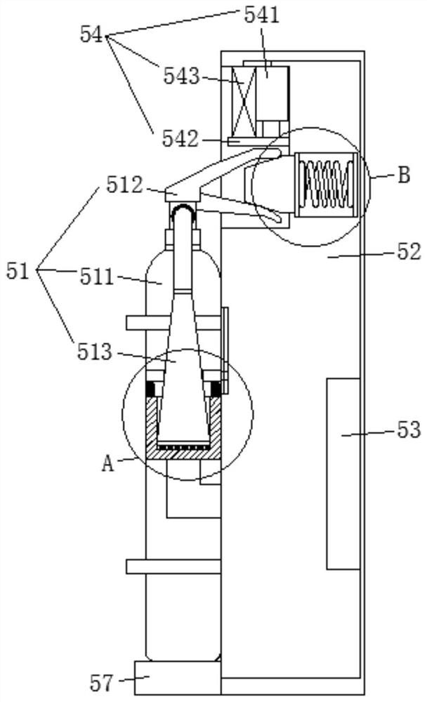
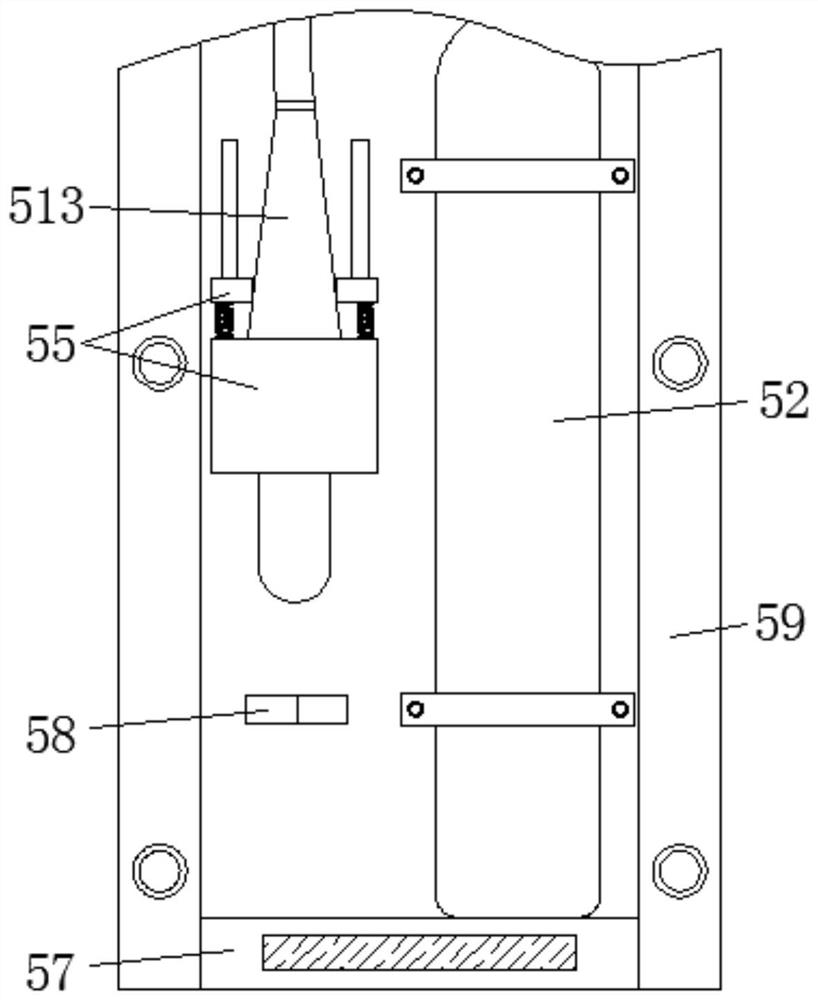
[0043] As an embodiment, the sealing connection mechanism 55 includes a movable pressure ring 551 and a fixed sealing sleeve 553, and the pressure ring 551 is a U-shaped structure, and an elastic connector 552 is connected with the sealing sleeve 553, and the nozzle pipe 513 is in the shape of One end is large and the other end is small. The end with a large diameter is inserted into the sealing sleeve 553, and the U-shaped groove of the pressure ring 551 is smaller than the maximum diameter of the nozzle 513. A conduit 554 is connected between the sealing sleeve 553 and the fire extinguishing pipe 4. Based on this, the connection principle of the sealing connection mechanism 55 is as follows: the pressure ring 551 is pulled apart, and the elastic connecting member 552 is stretched, so that the distance between the pressure ring 551 and the sealing sleeve 553 increases, and the nozzle 513 is snapped into the pressure ring 551. In the U-shaped groove, align the end of the nozzle...


PUM


Abstract

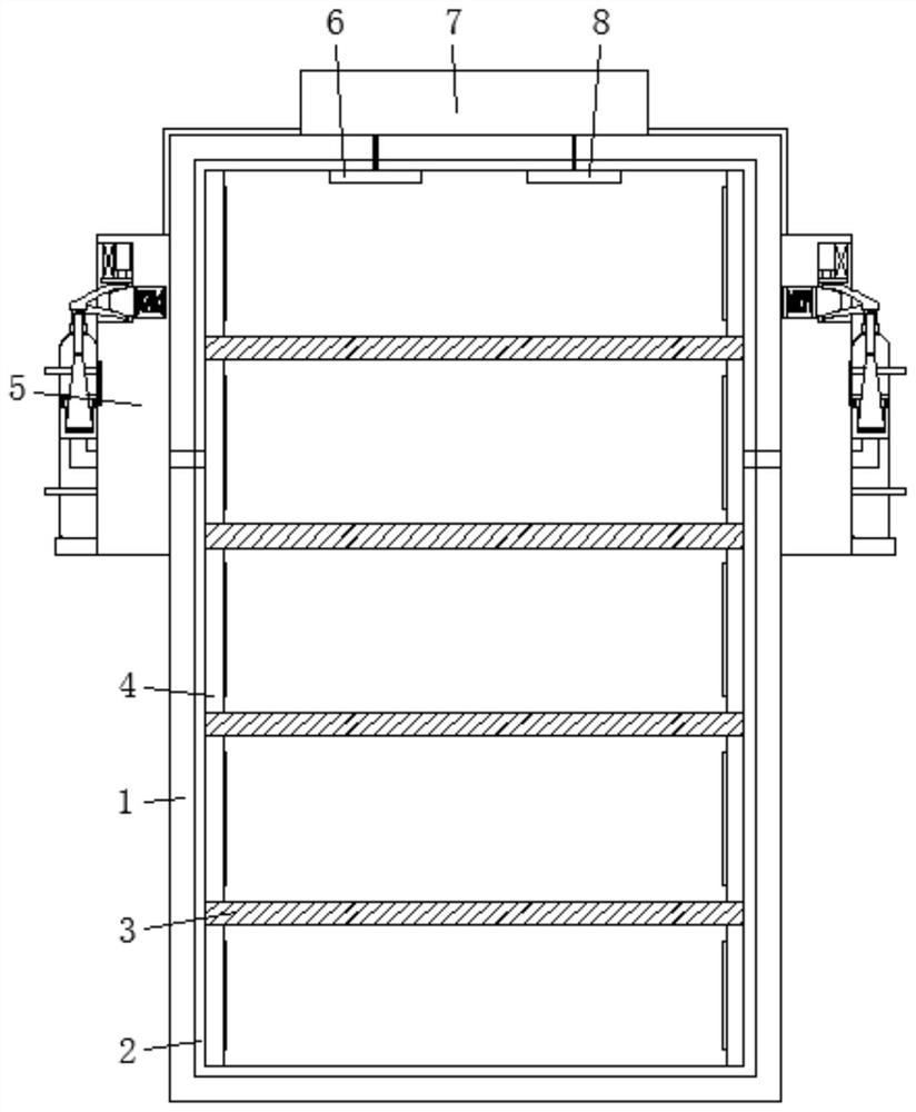
The invention belongs to the technical field of electrical control cabinets, and discloses a compartmentalized automatic electrical control cabinet with flame-retardant and fire-extinguishing functions, including an outer cabinet, a fire-extinguishing pipe installed inside the outer cabinet, a temperature sensor, a smoke sensor, and an outer cabinet. The fire extinguishing assembly and processing device outside the cabinet; the fire extinguishing pipeline and the fire extinguishing assembly are provided with at least one; the fire extinguishing assembly includes a fire extinguisher and a drive base, and the fire extinguisher is installed on the drive base; the processing device includes PLC processing and electrically connected to the drive base; real-time monitoring based on the temperature sensor and smoke sensor to determine whether there is a fire in the control cabinet, and if so, cooperate with the fire extinguishing device to realize timely fire extinguishing, so as to effectively reduce the loss when the control cabinet fires and the fire extinguishing device is based on a fire extinguishing pipeline, a common fire extinguisher and a driving base, and the production cost is low, and both the fire extinguisher and the driving base can be disassembled and replaced, and the use cost is low.

Description

technical field [0001] The invention belongs to the technical field of electrical control cabinets, and in particular relates to a compartmentalized automatic electrical control cabinet with flame-retardant and fire-extinguishing functions. Background technique [0002] With the rapid economic development, electrical automation systems play an important role in the fields of industry and national defense, including the security guarantee for electrical automation control cabinets. The control cabinet is a power supply device used to provide power for power equipment. During the working process, its internal electronic components will generate a lot of heat. The traditional heat dissipation method uses vents or cooling fans, which has a slow heat dissipation speed and cannot dissipate heat in a timely manner. Excluded, resulting in low operating efficiency of components, which will lead to aging of electrical components in the long run, and even cause electrical components to...

Claims


Application Information

Patent Timeline
Patent Type & Authority Patents(China)
IPC IPC(8): H05K5/00H05K5/02H05K5/06A62C3/16A62C37/40
CPCH05K5/02H05K5/0247H05K5/0017H05K5/06A62C3/16A62C37/40
Inventor 孙彦超樊明龙陈琳龚晨
Owner 广东盛银新能源科技有限公司
Learn More