Rapid flotation device

A flotation device, fast technology, applied in flotation, solid separation, etc., can solve the problem of long beneficiation process

Inactive Publication Date: 2020-04-17
TIBET HUATAILONG MINING DEV
View PDF6 Cites 0 Cited by
  • Summary
  • Abstract
  • Description
  • Claims
  • Application Information

AI Technical Summary

Problems solved by technology

[0003] The beneficiation of the prior art needs to go through multiple screenings, and the rough ore after preliminary screening of the raw ore needs to be screened at least twice before it can become a qualified concentrate, and the beneficiation process is long.

Method used


Image

  • Rapid flotation device
  • Rapid flotation device

Examples


Embodiment Construction

[0021] The core of the present invention is to provide a fast flotation device, which can quickly separate concentrate from raw ore pulp.

[0022] In order to enable those skilled in the art to better understand the technical solution of the present invention, the fast flotation device of the present invention will be described in detail below in conjunction with the accompanying drawings and specific implementation methods.

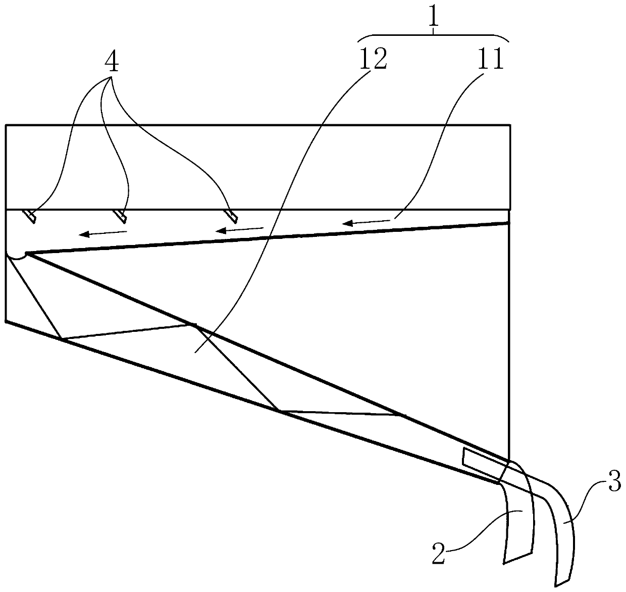
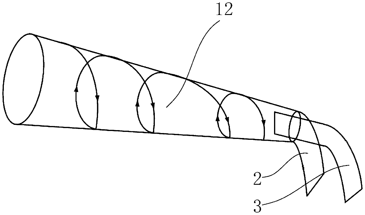
[0023] Such as figure 1 Shown is a structural schematic diagram of a specific embodiment of the fast flotation device provided by the present invention; the device includes a flotation chute 1 docked with a bubble scraper, and the flotation chute 1 plays the role of diverting pulp, and the flotation chute 1 is inclined. The top entrance of the flotation chute 1 is used to receive the foam-containing pulp scraped by the bubble scraping machine and guide the pulp to flow downward. The pulp flows downward in the flotation chute 1 under the action of gravity...


PUM


Abstract

The invention discloses a rapid flotation device which comprises a flotation chute which is in butt joint with a foam scraping machine, and is obliquely arranged and used for guiding ore pulp from topto bottom; a top end inlet of the flotation chute is used for receiving foam-containing ore pulp scraped by the foam scraping machine, and the ore pulp flows under the flow guide of the flotation chute; a bottom outlet of the flotation chute is in butt joint with a concentrate pipe and a coarse ore pipe; the density of metal concentrate in the ore pulp and the density of ore in the ore pulp are different, so that ore pulp is layered in the flowing process in the flotation chute, the concentrate pipe is used for receiving the concentrate separated out from the flotation chute, the coarse ore pipe is used for receiving the coarse ore separated out from the flotation chute, the concentrate is separated out from the ore pulp, the concentrate can be directly used, the raw ore screening processis shortened, and the concentrate can be rapidly separated out from the raw ore pulp.

Description

technical field [0001] The invention relates to the technical field of mineral processing equipment, and further relates to a fast flotation device. Background technique [0002] Flotation refers to the use of a surfactant-foaming agent that can generate a large number of bubbles. When air is introduced into the water or the air enters the water due to the agitation of the water, the hydrophobic end of the surfactant faces the air bubbles at the air-liquid interface. One side is oriented, and the hydrophilic end is still in the solution, forming bubbles; the other surfactant (generally cationic surfactants, including aliphatic amines) that acts as a trap is adsorbed on the surface of the solid mineral powder. Adsorption has a certain selectivity depending on the nature of the minerals. Using the lattice defects on the crystal surface, the outward hydrophobic end is partially inserted into the air bubbles. During the flotation process, the air bubbles may take away the specif...

Claims


Application Information

Patent Timeline
IPC IPC(8): B03D1/14
CPCB03D1/14B03D1/1443
Inventor 解钊刘子龙刘璇遥李磊张金刚王鹤强王海青吴忠伟胡其旭李玉山
Owner TIBET HUATAILONG MINING DEV
Why Eureka
Try Eureka