Automatic cutting device for square plate section at end of pipe pile.

A technology of automatic cutting device and pipe pile, which is applied to shearing devices, accessories of shearing machines, maintenance and safety accessories, etc. , increase the accuracy, provide the effect of working efficiency

Inactive Publication Date: 2020-04-17
浙江弘源金属制品股份有限公司
View PDF5 Cites 2 Cited by
  • Summary
  • Abstract
  • Description
  • Claims
  • Application Information

AI Technical Summary

Problems solved by technology

[0003] Before the end plate is welded into an integration with the pipe pile, it needs to be molded, cooled, molded, cut into pieces, punched, edged, cleaned and packaged, etc., but the existing end plate When cutting into pieces, the cutting device used has a complex structure and is inconvenient to operate. At the same time, in the cutting process, only the end plates can be cut out one by one, which reduces the work efficiency. In the cutting process, the cutting blade and the end plate The friction between the plates will increase the temperature of the cutting blade surface, which will affect the damage of the cutting blade, and it needs to be replaced frequently, which increases the cost input and reduces the action. efficiency, so it is necessary to provide an automatic cutting device for square plate segments at the end of pipe piles to solve the above problems

Method used


Image

  • Automatic cutting device for square plate section at end of pipe pile.
  • Automatic cutting device for square plate section at end of pipe pile.
  • Automatic cutting device for square plate section at end of pipe pile.

Examples


Embodiment 1

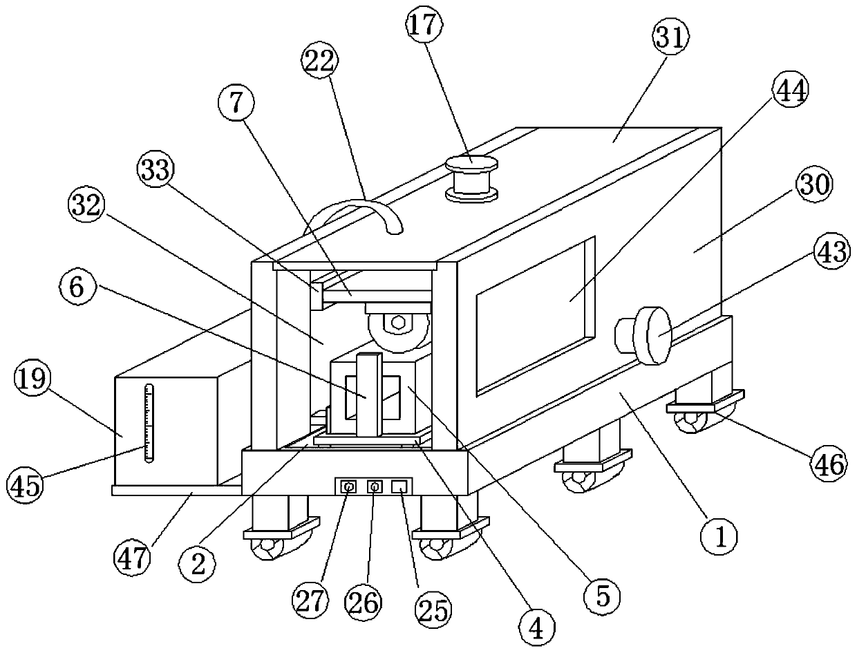
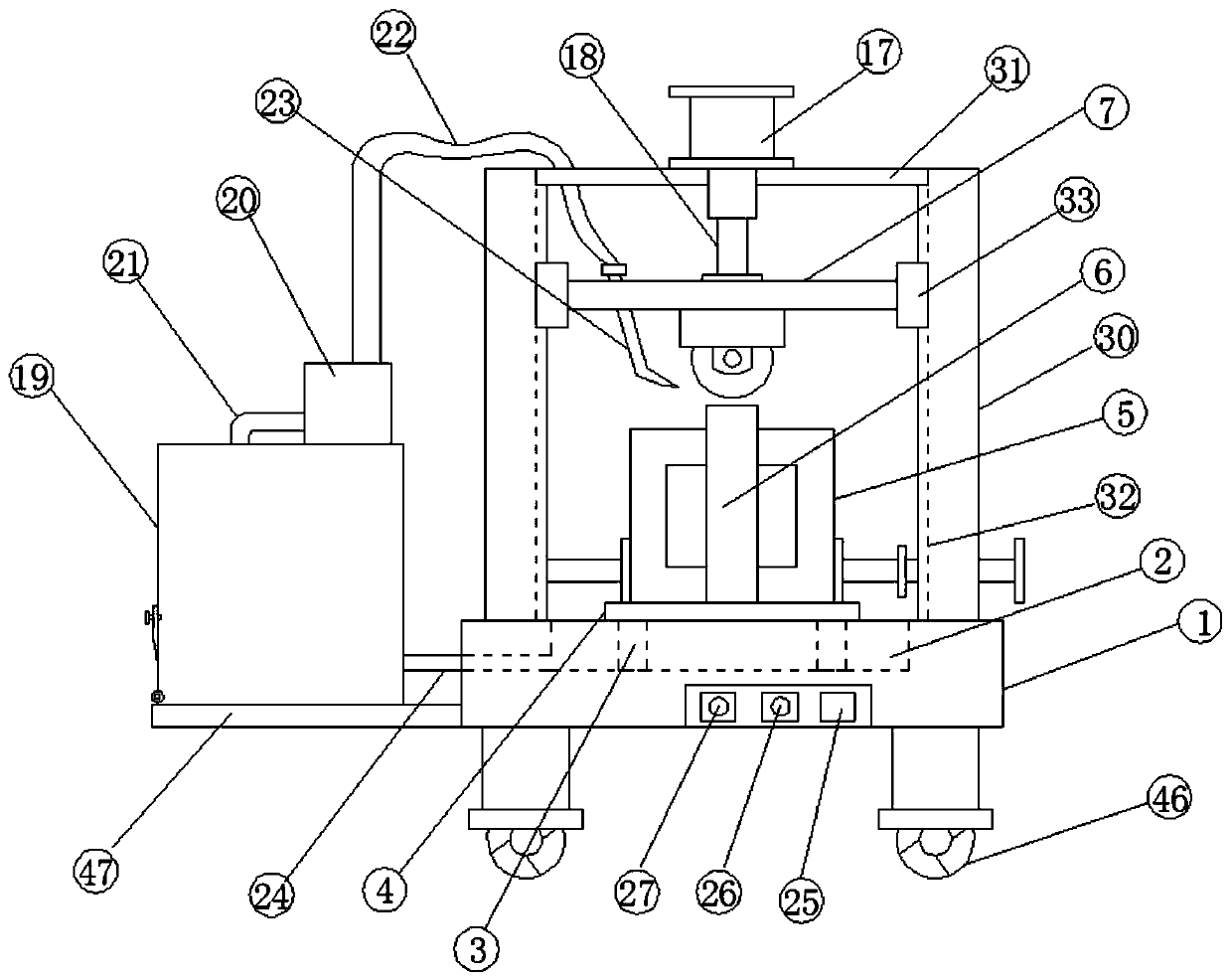
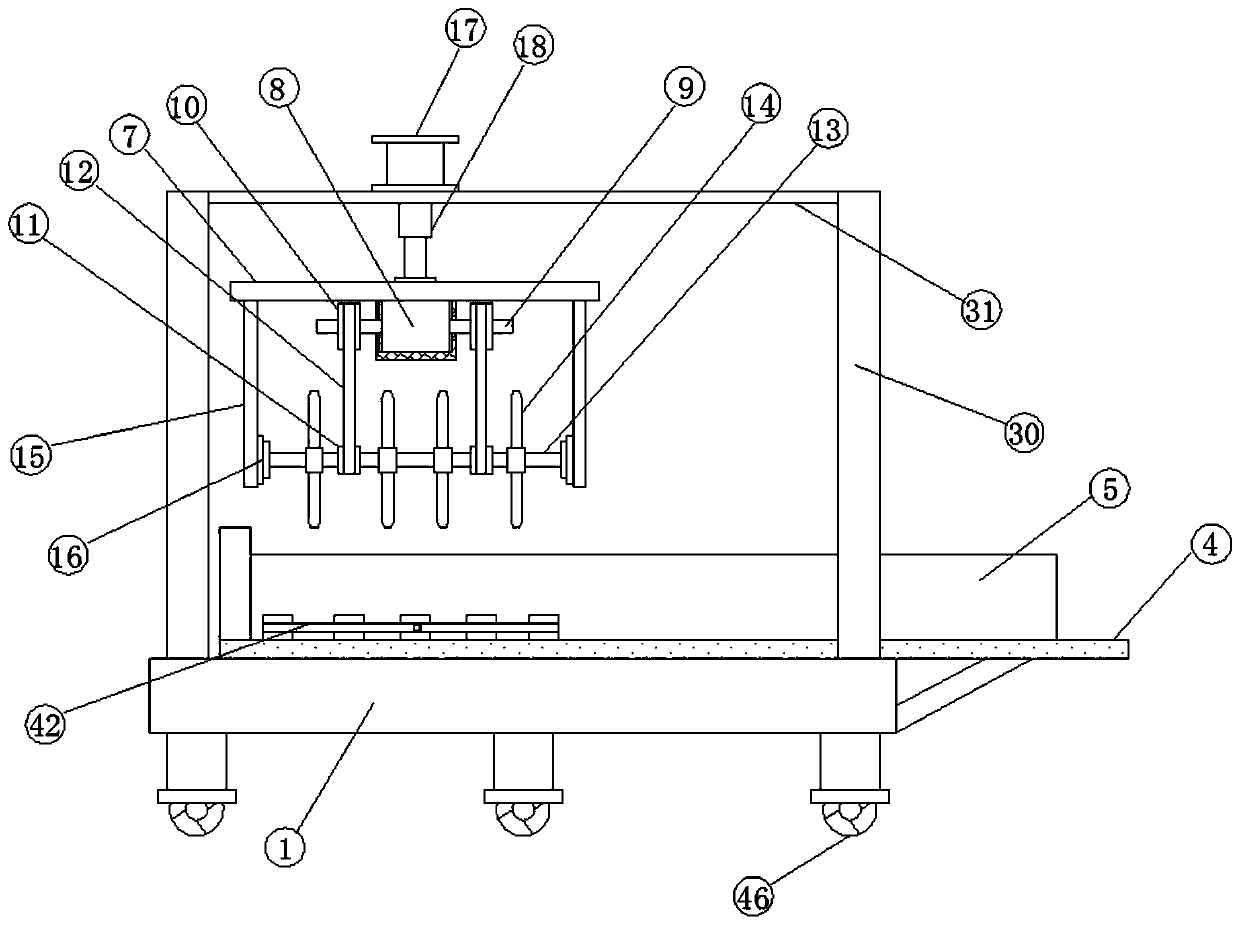
[0032] see Figure 1-5 , according to an embodiment of the present invention, an automatic cutting device for square plate segments at the end of pipe piles includes an operating table 1, a water receiving tank 2 is provided in the middle of the operating table 1, and a support is fixed inside the water receiving tank 2 Column 3, the end of the support column 3 away from the water tank 2 is fixed with a placement table 4, the placement table 4 is provided with a square plate 5, and the two sides of the square plate 5 are provided with clamping devices, so One end of the placement table 4 is fixedly provided with a limit baffle 6, a cutting device is provided above the square plate 5, and the cutting device includes a lifting plate 7, and a side of the lifting plate 7 is provided with a biaxial motor 8, The output end of described biaxial motor 8 is provided with rotating shaft 9, and first gear 10 is fixedly arranged on described rotating shaft 9, and the below of described fi...

Embodiment 2

[0034] see figure 1 , 2 , 3, 5, for the clamping device, the clamping device includes several clamping blocks 41, one end of the clamping block 41 is fixedly provided with a connecting rod, and the end of the connecting rod far away from the clamping block 41 is connected with The push plate 42 is fixedly connected, the end of the push plate 42 away from the connecting rod is provided with a threaded rod 43, the threaded rod 43 runs through the support device, and the threaded rod 43 is threadedly connected with the support device, One end of the threaded rod 43 is connected to the push plate 42 through the second bearing seat, and the side of the square plate 5 away from the clamping block 41 is provided with an auxiliary device, and the clamping device can be placed on the placement table 4 The square plate plays the role of clamping, so as to realize the effect of stability when cutting the square plate 5, avoid shaking in the cutting process, greatly increase the accuracy...

Embodiment 3

[0036] see figure 1 , 2 , 5, for the auxiliary device, the auxiliary device includes a fixed rod 28, one side of the fixed rod 28 is fixed with a stopper 29, and the end of the stopper 29 away from the fixed rod 28 is in contact with the side The plate 5 contacts, and the end of the fixed rod 28 away from the stopper 29 is fixedly connected with the support device. The auxiliary device can play the role of limit resistance when the clamping device clamps the opposite plate, increasing the clamping force. stability.


PUM


Abstract

The invention discloses an automatic cutting device for a square plate section at end of a pipe pile. The automatic cutting device comprises an operation table, wherein a water receiving groove is formed in the middle of the operation table; a supporting column is fixedly arranged in the water receiving groove; a placing table is fixedly arranged at the end, far away from the water receiving groove, of the supporting column; a square plate is arranged on the placing table; clamping devices are arranged on the two sides of the square plate; a limiting baffle is fixedly arranged at one end of the placing table; a cutting device is arranged above the square plate; the cutting device comprises a lifting plate; a double-shaft motor is arranged on one side of the lifting plate; rotating shafts are arranged at the output ends of the double-shaft motor; first gears are fixedly arranged on the rotating shafts; second gears are arranged below the first gears; and the first gears are connected with the second gears through racks. The automatic cutting device has the beneficial effects that the device is simple in structure and convenient to operate and use, the working efficiency is greatly improved, the cost investment is reduced, and the use safety of a cutting blade is improved.

Description

technical field [0001] The invention relates to the field of cutting equipment design, in particular to an automatic cutting device for square plate segments at the end of pipe piles. Background technique [0002] With the rapid development of urban construction, pipe piles have been widely used in highways, bridges, wharf construction, buildings, industrial plants, and power plants. As an important component for connecting and fixing prestressed steel bars at both ends of the pipe pile, the end plate plays an important role in connecting the upper and lower pipe piles to form an overall structure. There are higher requirements, the end plates are generally circular end plates and square end plates, and the end plates and pipe piles are fixedly connected by welding. [0003] Before the end plate is welded and integrated with the pipe pile, it needs to be molded, cooled, molded, cut into pieces, punched, edged, cleaned and packaged, etc., but the existing end plate When cut...

Claims


Application Information

Patent Timeline
Patent Type & Authority Applications(China)
IPC IPC(8): B23D19/06B23D33/00B23D33/02B23Q11/10
CPCB23D19/06B23D33/00B23D33/02B23Q11/10B23Q11/1069
Inventor 俞敏芳
Owner 浙江弘源金属制品股份有限公司
Why Eureka
Try Eureka