Manufacturing method of subway vehicle chassis

A manufacturing method and chassis technology, which is applied to the chassis, manufacturing tools, railway car body parts, etc., can solve the problems of long manufacturing cycle and low product quality, and achieve the effect of saving operating time and improving assembly

Active Publication Date: 2020-04-17
河北京车轨道交通车辆装备有限公司
View PDF8 Cites 3 Cited by
  • Summary
  • Abstract
  • Description
  • Claims
  • Application Information

AI Technical Summary

Problems solved by technology

[0006] The purpose of the present invention is to improve the deficiencies of the existing schemes, and propose a manufacturing process suitable for the chassis side beams and

Method used


Image

  • Manufacturing method of subway vehicle chassis
  • Manufacturing method of subway vehicle chassis
  • Manufacturing method of subway vehicle chassis

Examples


Embodiment 1

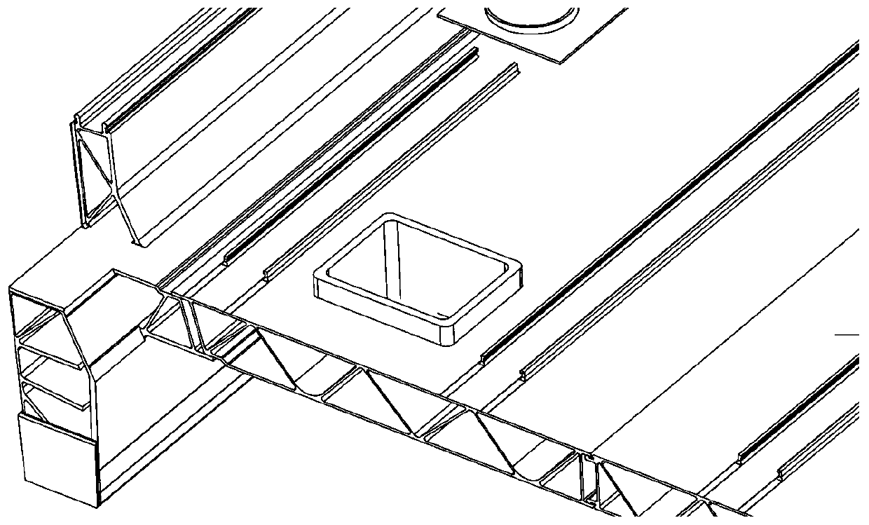
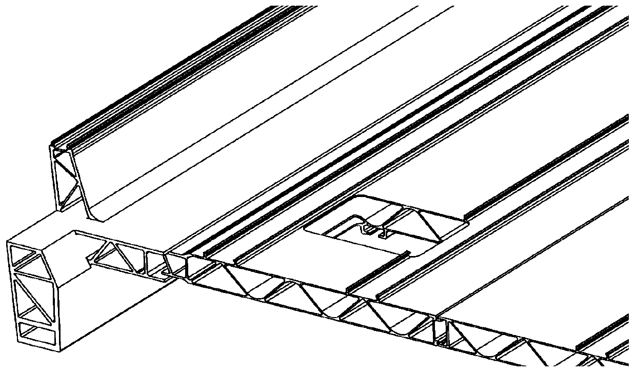
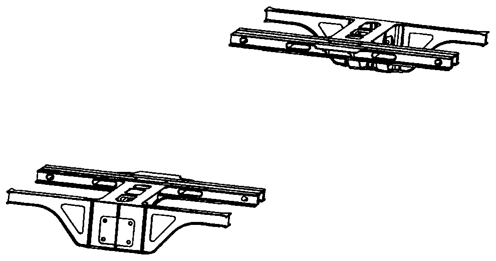
[0035] like Figure 10-13 As shown, the manufacturing process of the subway car underframe in this embodiment, wherein the parts to be assembled include: floor profile one 1, floor profile two 2, floor profile three 3, floor profile four 4, floor profile five 5, bottom profile The frame side beam I6, the bottom frame side beam II7, the traction pillow 9 and the bottom frame end beam 11 mainly include the following steps:

[0036] like Figure 10 As shown, step 1: firstly position the frame side beam I6, and base on the frame side beam I6, and sequentially place floor profile one 1, floor profile two 2, floor profile three 3, floor profile four 4, and floor profile five 5 Assemble, and then assemble the underframe side beam II7 with the outermost floor profile 55, and then weld the welds on both sides of the floor profile 33 in the middle, and finally take these two welds as the benchmark Weld the remaining welds outward to obtain the prefabricated underframe 10;

[0037] St...

Embodiment 2

[0046] Compared with the first embodiment, the manufacturing process of the subway vehicle underframe in this embodiment is only different in that: the floor profile and the side beam of the underframe in the first step are assembled by overlapping.

[0047] In the manufacturing method of the subway vehicle chassis according to the embodiment of the present invention, the two side chassis side beams are adjusted to the automatic welding tire position of the floor profile for overall assembly, and such chassis side beams are connected with the adjacent single floor profile The plug-in assembly is much less difficult than the assembly of the side beams of the bottom frame and the overall floor components; a total of four welds on the front and back sides of the side beams of the bottom frame are manually welded on the bottom frame assembly welding tool, and adjusted From the overall assembly and automatic welding on the floor welding tool, the welding operation efficiency has bee...


PUM


Abstract

The invention discloses a method for manufacturing a subway vehicle chassis, which mainly comprises the following steps of: 1, a chassis boundary beam I, a plurality of floor profiles and a chassis boundary beam II are assembled and welded to obtain a prefabricated chassis; 2, the prefabricated chassis is taken out of a jig to be adjusted and repaired; 3, the adjusted and repaired prefabricated chassis is in a reverse installation state, a traction bolster and a chassis end beam are assembled and welded, and an intermediate chassis is obtained; 4, the welded intermediate chassis is transferredout of the jig, and flame adjustment and repair are conducted; and 5, the adjusted middle chassis is carried out, and accessories are installed to obtain the subway vehicle chassis. Before parts suchas the traction bolster, the end beam and the like are assembled and welded, the chassis boundary beams and the floor profile are assembled; therefore, the assembly of the chassis boundary beams andthe floor profile can meet two different assembly modes of inserting connection and overlapping connection, the problem that the floor cannot be placed into a mould and assembled after the boundary beams are positioned in the connection mode of the chassis boundary beams and the floor of an inserting connection structure is solved, and the manufacturing period of the chassis is effectively shortened.

Description

technical field [0001] The invention belongs to the technical field of vehicle manufacturing, and more specifically relates to a manufacturing process method for a subway vehicle underframe. Background technique [0002] The existing subway car body chassis is generally assembled and welded by parts such as traction pillows, ends, and seven long profiles; among them, the five floor profiles are generally connected in the form of butt joints, and the floors on both sides The profiles and the side beams of the chassis are connected in the form of lap joints (structures such as figure 1 and image 3 shown); according to the connection mode of conventional underframe side beams and floor laps, the manufacturing process of the underframe parts is: the corbel beam is placed into the front tire positioning-the traction is slowed into the front tire positioning-the underframe side beam is inserted into the front tire positioning-pulling Pillow cushioning, side beam point fixing, w...

Claims


Application Information

Patent Timeline
IPC IPC(8): B23K37/00B23P19/00B61F1/00
CPCB23K37/00B23P19/00B61F1/00
Inventor 王俊玖杨利军齐振国侯秀娟尹德猛
Owner 河北京车轨道交通车辆装备有限公司
Why Eureka
Try Eureka