Plate cutting and positioning device

A positioning device and plate technology, which is applied to positioning devices, manufacturing tools, metal processing machinery parts, etc., can solve the problems of low work efficiency of plate positioning methods, and achieve the effects of simple operation, improved work efficiency, and enhanced positioning effect.

Active Publication Date: 2020-12-22
重庆金华兴门业有限公司
View PDF9 Cites 0 Cited by
  • Summary
  • Abstract
  • Description
  • Claims
  • Application Information

AI Technical Summary

Problems solved by technology

[0004] The present invention intends to provide a plate cutting and positioning device to solve the problem of low working efficiency of the current plate positioning method

Method used


Image

  • Plate cutting and positioning device
  • Plate cutting and positioning device
  • Plate cutting and positioning device

Examples


Embodiment 1

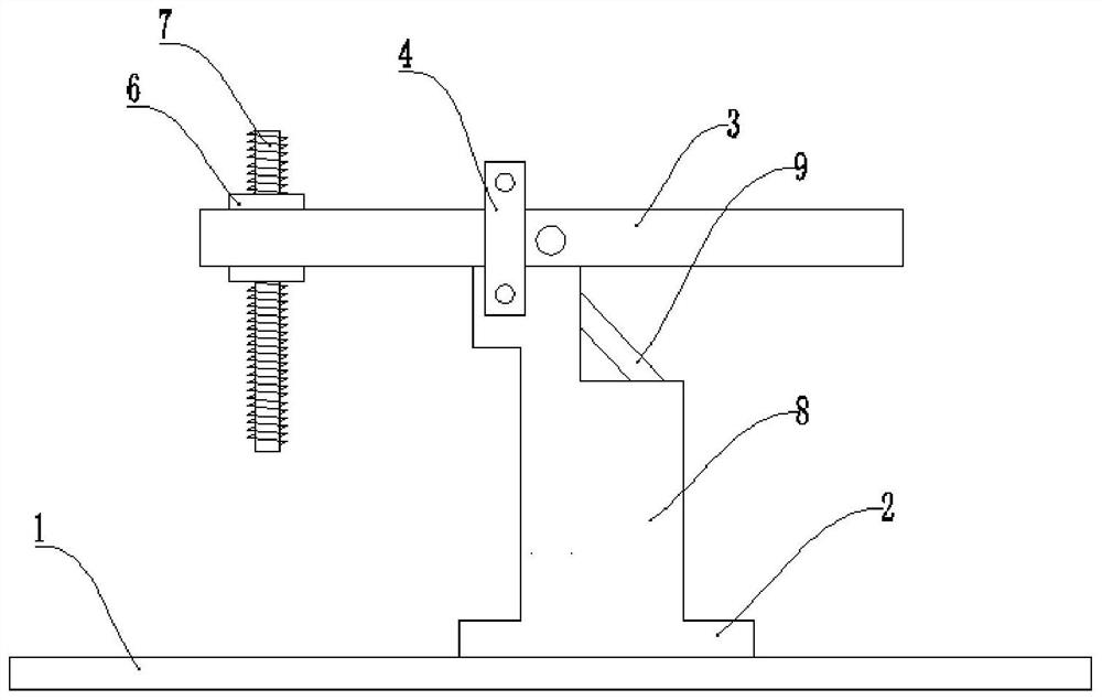
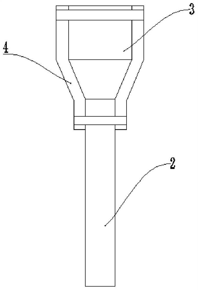
[0037] Basic as attached figure 1 , attached figure 2 And attached image 3 As shown: the plate cutting positioning device, including machine base 1, three positioning mechanisms for pressing both ends of the plate are equidistantly arranged on machine base 1 along the horizontal direction, the positioning mechanism includes support arm 2 and swing arm 3, support arm 2 and machine The seat 1 is fixedly connected, the middle part of the swing arm 3 is hinged with the top of the support arm 2, and the swing arm 3 and the support arm 2 are perpendicular to each other.

[0038] The support arm 2 is provided with a limit mechanism for limiting the position of the swing arm 3. The limit mechanism includes iron sheets 4 fixed on both sides of the support arm 2. The upper ends of the two iron sheets 4 are also affixed. The distance between 4 gradually decreases from top to bottom, and the swing arm 3 swings in the gap between the two iron pieces 4; the width of the left end of the ...

Embodiment 2

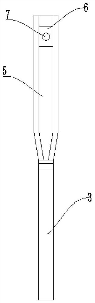
[0045] Basic as attached Figure 4 And attached Figure 5 As shown: the structure and implementation of Embodiment 2 are basically the same as Embodiment 1, the difference is that both sides of the slider 6 are provided with a stop mechanism for stopping the slider 6, and the stop mechanism includes the same The piston cylinder 10 fixed to the slider 6 and the piston plate 11 slidingly connected with the piston cylinder 10; the piston cylinder 10 is connected with an air outlet pipe 12; both sides of the chute 5 are provided with guide holes 13 along the length direction of the chute 5 The air outlet pipe 12 is slidingly connected with the guide hole 13, and the lower end of the air outlet pipe 12 away from the end of the piston cylinder 10 is connected with an air bag 14 for tightening the slider 6; First one-way valve 15; On the side wall of piston cylinder 10, be connected with inlet pipe 16, and the second one-way valve 17 that one-way flow to piston cylinder 10 direction...


PUM


Abstract

The invention relates to the field of plate cutting, and discloses a positioning device for plate cutting. The positioning device comprises a stand; the stand is provided with at least two positioningmechanisms used for holding down the two ends of a plate; each positioning mechanism includes a supporting arm and a swing arm; each supporting arm is fixedly connected with the stand; the middle part of each swing arm is hinged with the top part of the corresponding supporting arm; and each supporting arm is provided with a limiting mechanism used for limiting the corresponding swing arm. According to the scheme, the positioning device mainly solves the problem that the working efficiency is low by adopting a plate positioning way at present.

Description

technical field [0001] The invention relates to the field of plate cutting. Background technique [0002] Panels are flat rectangular building material panels of standard sizes used in the construction industry as components for door panels, walls, ceilings or floors. [0003] At present, the production process of the door panel involves the cutting of the panel. Before cutting the panel, the panel needs to be positioned. The traditional positioning method is: place the panel on the machine base, and then fix the nail according to the position of the panel. On the machine base, there are two nails, and the two nails are located on both sides of the plate, and then the nails are bent to make the nails bend to the plate, so as to realize the positioning of the plate; but the above positioning method is suitable for different thicknesses. 1. For plates of different lengths, it is necessary to re-determine the location of the nails every time, fix the nails again, and knock the...

Claims


Application Information

Patent Timeline
Patent Type & Authority Patents(China)
IPC IPC(8): B23Q3/06
CPCB23Q3/06B23Q3/062
Inventor 周维
Owner 重庆金华兴门业有限公司
Why Eureka
Try Eureka