Pneumatic clamping device

A technology of clamping device and air pressure, applied in the field of intelligent processing equipment, can solve the problems of low work efficiency, increase the production cost of clamping device, reduce the working efficiency of clamping, etc.

Inactive Publication Date: 2020-04-17
张海旦
View PDF9 Cites 8 Cited by
  • Summary
  • Abstract
  • Description
  • Claims
  • Application Information

AI Technical Summary

Problems solved by technology

[0003] With the development of science and technology and the continuous improvement of productivity, the machine tools in the existing market are generally CNC machine tools. Generally, automatic clamping devices are installed in CNC machine tools. Most of the existing automatic clamping devices are hydraulic clamping devices and pneumatic clamping devices. Two types, the pneumatic clamping device has the characteristics of lower cost compared with the hydraulic clamping device, and its ma

Method used


Image

  • Pneumatic clamping device
  • Pneumatic clamping device

Examples


Example Embodiment

[0025] The present invention will be further described in detail below with reference to the drawings and specific embodiments.

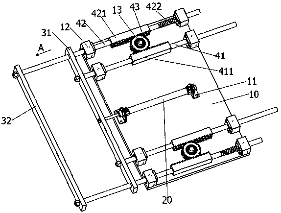
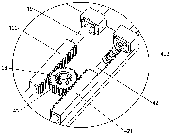
[0026] See Figure 1-2 As shown, the present invention provides a pneumatic clamping device, which includes a fixed plate 10, an air cylinder 20, a transmission assembly and a clamping assembly.

[0027] The cylinder 20 is fixedly arranged on the fixed plate 10, and a fixed seat 11 is arranged on the fixed plate 10. Two ends of the cylinder 20 are respectively fixedly connected to the fixed seat 11, and the output end of the cylinder 20 can be moved telescopically in the fixed seat 11.

[0028] The clamping assembly includes a first clamping plate 31 and a second clamping plate 32. The first clamping plate 31 and the second clamping plate 32 are arranged parallel and opposite to each other. The first clamping plate 31 is fixedly connected to the output end of the cylinder 20. The cylinder 20 drives the first clamping plate 31 along the Moved in the first ...


PUM


Abstract

The invention provides a pneumatic clamping device. The pneumatic clamping device comprises a fixing plate, an air cylinder, transmission assemblies and a clamping assembly; the clamping assembly comprises a first clamping plate and a second clamping plate, the first clamping plate is fixedly connected with the output end of the air cylinder, the air cylinder drives the first clamping plate to move in the first direction, and the transmission assemblies are arranged on the two sides of the air cylinder; each transmission assembly comprises a first sliding rod, a second sliding rod and a transmission gear, the ends of the first sliding rods are fixedly connected with the first clamping plate, and the ends of the second sliding rods are fixedly connected with the second clamping plate; and the transmission gears are rotatably connected with rotation shafts fixedly arranged on the fixing plate and mesh with first racks and second racks. The first racks move to drive the transmission gearsto rotate around the rotation shafts to drive the second racks to move in the direction opposite to that of the first racks, then driving on the first clamping plate and driving on the second clamping plate are synchronously achieved, and clamping action on workpieces in the same degree-of-freedom direction is achieved.

Description

technical field [0001] The invention relates to the technical field of intelligent processing equipment, in particular to a pneumatic clamping device. Background technique [0002] In the machining process, in order to ensure the machining accuracy, the workpiece is fixed so that it occupies a certain position and the process equipment for processing or testing is the clamping device of the machine tool. [0003] With the development of science and technology and the continuous improvement of productivity, the machine tools in the existing market are generally CNC machine tools. Generally, automatic clamping devices are installed in CNC machine tools. Most of the existing automatic clamping devices are hydraulic clamping devices and pneumatic clamping devices. Two types, the pneumatic clamping device has the characteristics of lower cost compared with the hydraulic clamping device, and its market share is gradually increasing, but the existing pneumatic clamping has low work...

Claims


Application Information

Patent Timeline
IPC IPC(8): B23Q3/08
CPCB23Q3/08B23Q2703/04
Inventor 张海旦
Owner 张海旦
Why Eureka
Try Eureka