High-voltage transmission line rescue robot and using method

A technology of high-voltage transmission lines and rescue robots, which is applied in the direction of overhead lines/cable equipment, manipulators, manufacturing tools, etc., can solve the problems of high energy consumption, small load capacity of robots, and many driving joints, so as to prevent shaking and save rescue time , the effect of easy disassembly

Active Publication Date: 2020-04-17
CHINA THREE GORGES UNIV
View PDF8 Cites 7 Cited by
  • Summary
  • Abstract
  • Description
  • Claims
  • Application Information

AI Technical Summary

Problems solved by technology

Existing robots that can cross obstacles can be divided into line patrol robots for detecting line faults, deicing robots for clearing line ice accumulation, and rescue robots for rescue operations. The control is complicated, and a lot of batteries are required, which increases the weight of the robot itself; second, the load capacity of these robots is relatively small, and they cannot undertake the task of manned rescue

Method used


Image

  • High-voltage transmission line rescue robot and using method
  • High-voltage transmission line rescue robot and using method
  • High-voltage transmission line rescue robot and using method

Examples


Embodiment 1

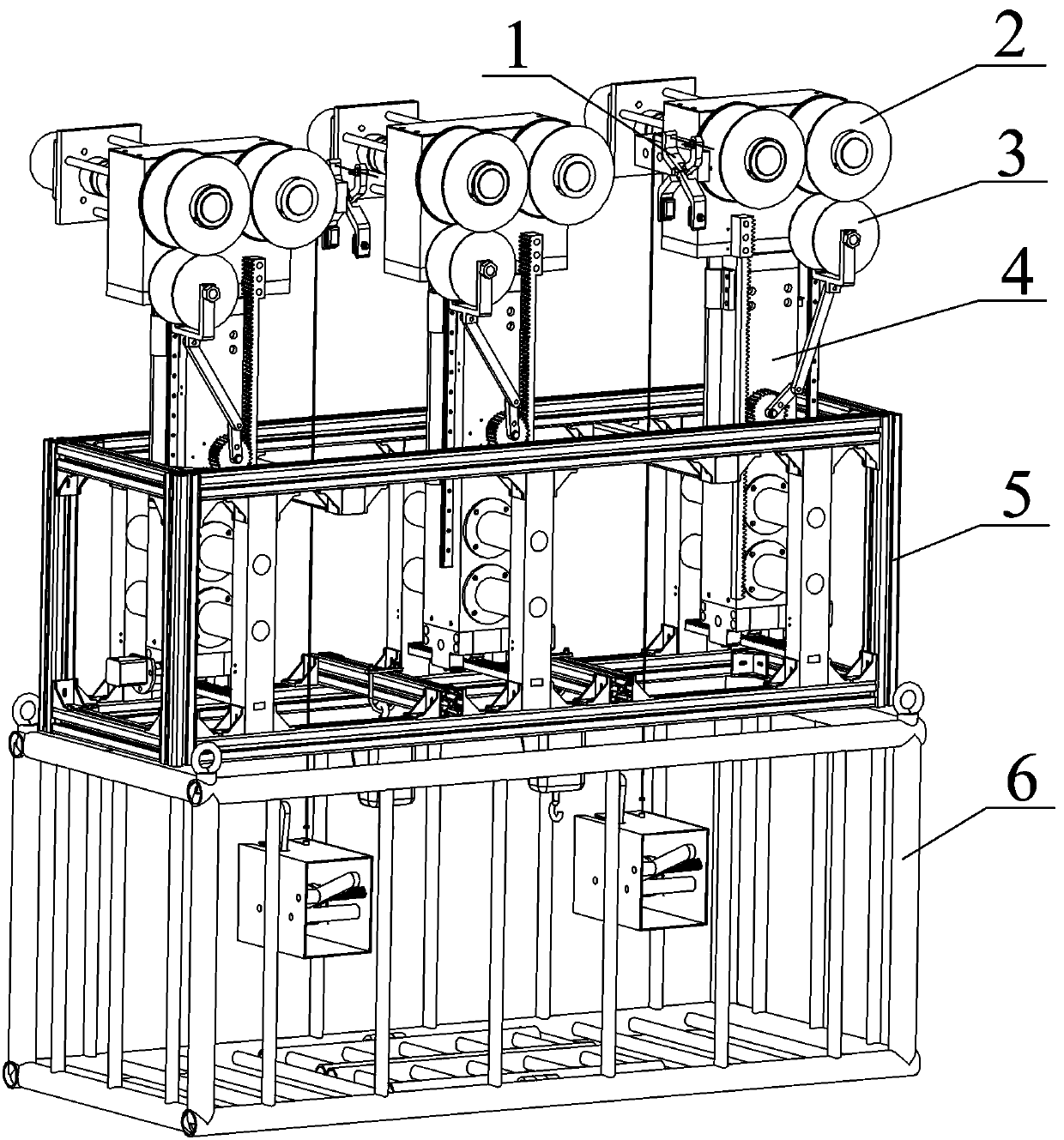
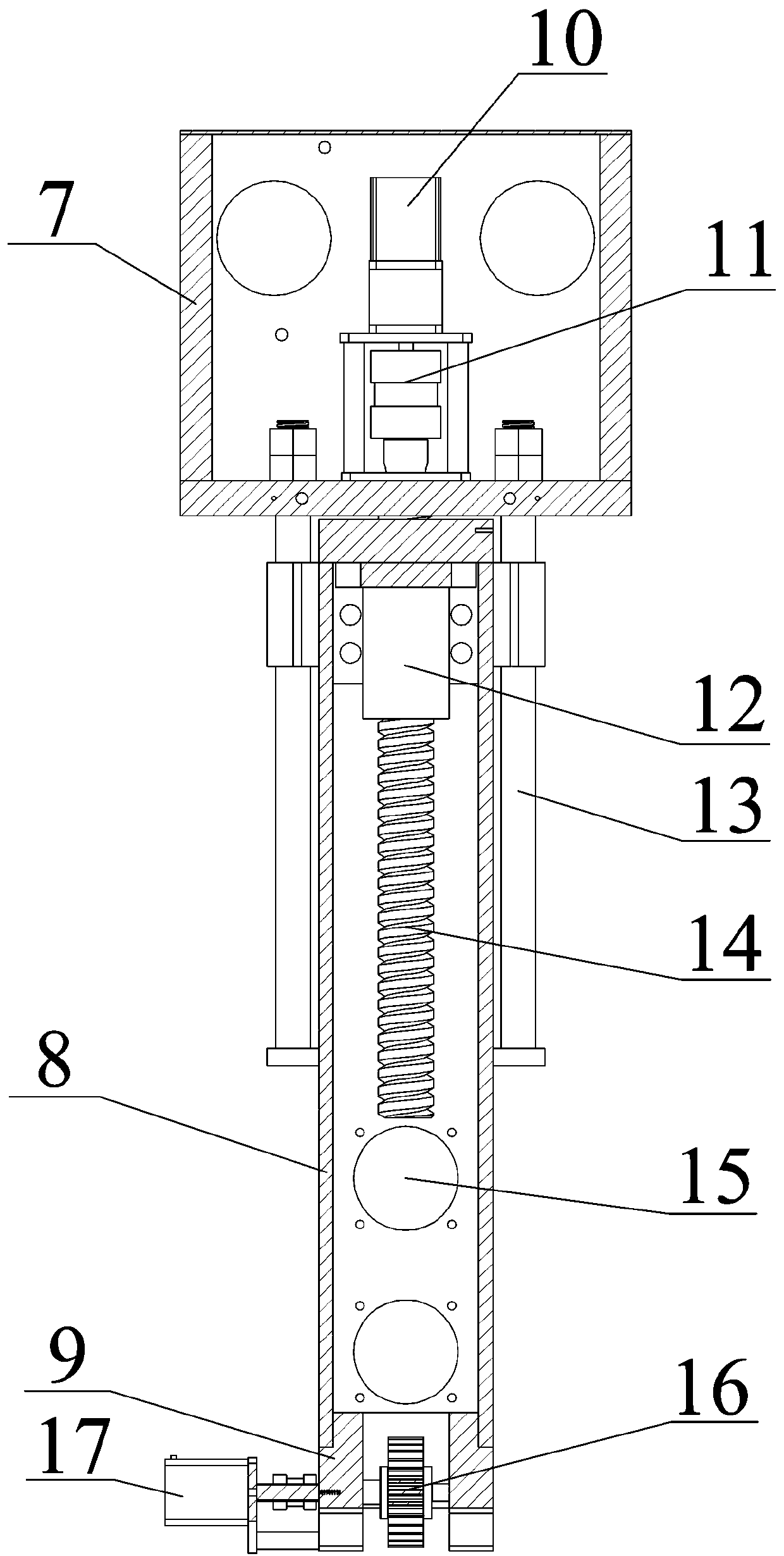
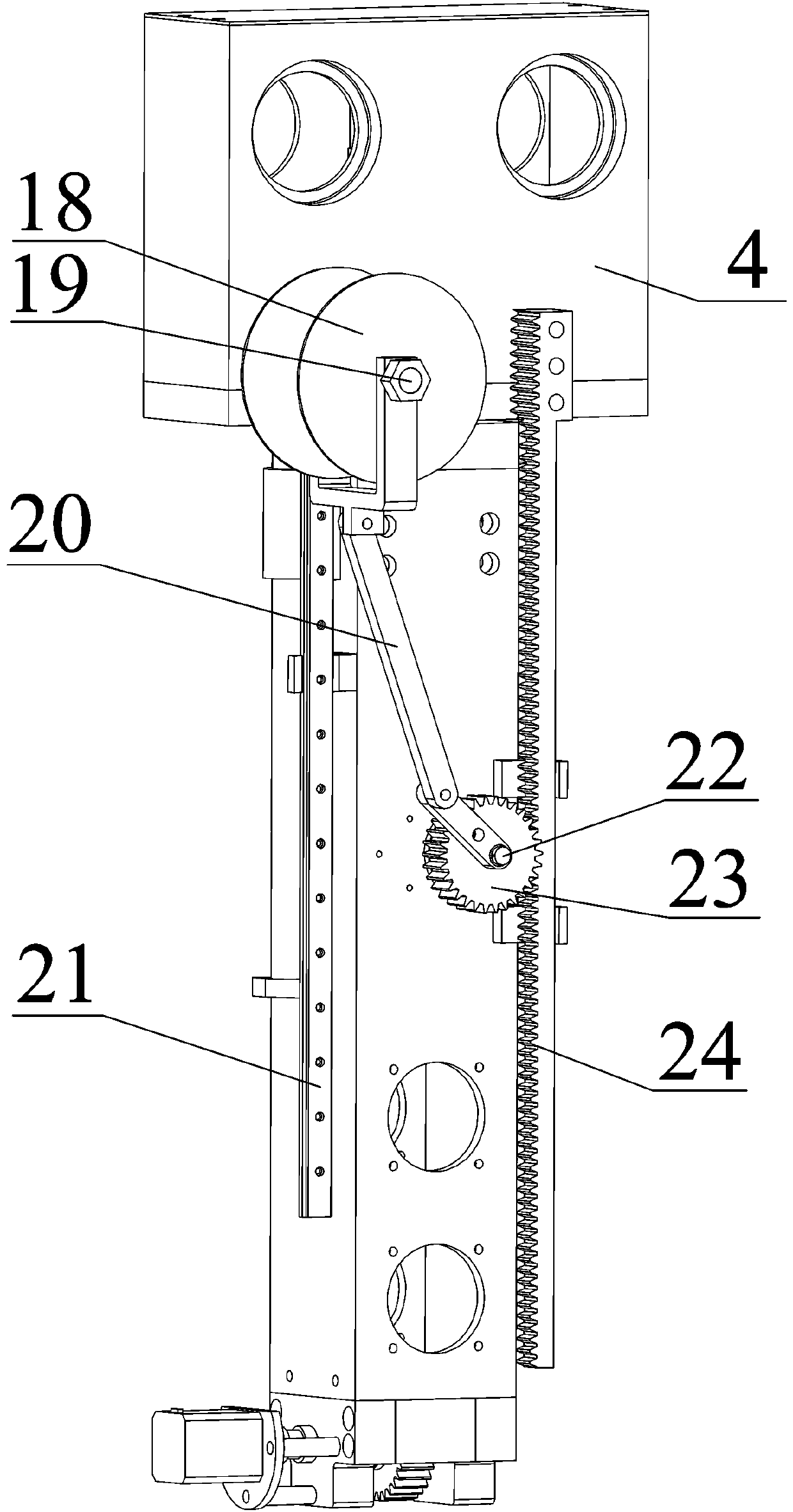
[0034] Such as figure 1 As shown, a high-voltage transmission line rescue robot is composed of a braking mechanism 1, a traveling mechanism 2, a clamping mechanism 3, a mechanical arm 4, a support frame 5 and a hanging basket 6. Wherein, the mechanical arm 4 is composed of three parts: the upper part 7 of the mechanical arm, the middle part 8 of the mechanical arm and the lower part 9 of the mechanical arm; The clamping and loosening of the wires; the traveling mechanism 2 is installed on the upper part 7 of the mechanical arm to drive the whole robot to travel on the wires; the brake mechanism 1 is installed on the side of the upper part 7 of the mechanical arm. Three groups of mechanical arms 4 are installed side by side on the support frame 5, and the left and right movement of the mechanical arm 4 is realized by the gear 16 and the rack 45 between the mechanical arm bottom 9 and the support frame 5. Hanging basket 6 is a place for personnel to stay.

[0035] Such as fi...

Embodiment 2

[0042] The method for using the high-voltage transmission line rescue robot includes the following steps:

[0043] Step 1, when a dangerous situation occurs, quickly transport the rescue robot body and the hanging basket 6 to the pole tower closest to the operator's drop point;

[0044] In the second step, the rescue robot body and the hanging basket 6 are assembled together, and the screw motor 10 is started to make the upper part 8 of the mechanical arm rise for a certain distance. At this time, the traveling wheel 31 and the clamping wheel 18 will be separated due to the linkage effect;

[0045] Step 3, use the hoisting device to hoist the rescue robot on the high-voltage transmission line. After the traveling wheel 31 is hung on the line, start the screw motor 10, and clamp the wire between the traveling wheel 31 and the clamping wheel 18;

[0046] Step 4: Start the walking wheel motor 27 to allow the rescue robot to move towards the fallen worker. When encountering an obs...


PUM


Abstract

The invention provides a high-voltage transmission line rescue robot and a using method. The high-voltage transmission line rescue robot comprises support frames, and multiple groups of mechanical arms are mounted on the support frame. The mechanical arms each comprise a mechanical arm upper part, a mechanical arm middle part and a mechanical arm lower part, wherein the mechanical arm upper part is provided with a walking mechanism used for driving the whole robot to walk, the side face of the mechanical arm upper part is provided with a clamping mechanism used for being matched with the walking mechanism, and the side wall of the front end of the mechanical arm upper part is provided with a brake mechanism used for clamping a power transmission line. The multiple groups of mechanical armsare installed between the support frames in parallel, and left-right movement of the mechanical arms is realized through matching of gears and racks between the mechanical arm lower parts and the support frames.

Description

technical field [0001] The invention relates to the field of maintenance equipment for transmission cables, in particular to a high-voltage transmission line rescue robot and method. Background technique [0002] At present, the daily maintenance of high-voltage transmission lines is mainly completed through manual on-line inspections. When the operators are on-line inspections, if they fall from a high altitude due to unexpected conditions (such as sudden physical discomfort, weather changes), if there is no self-rescue ability, When other rescue methods (such as high-altitude rescue vehicles and helicopters) are difficult to approach the operator due to environmental and climatic reasons, a rescue robot that can cross obstacles and automatically approach the operator is needed for rescue. Existing robots that can cross obstacles can be divided into line patrol robots for detecting line faults, deicing robots for clearing line ice accumulation, and rescue robots for rescue ...

Claims


Application Information

Patent Timeline
Patent Type & Authority Applications(China)
IPC IPC(8): B25J11/00H02G1/02
CPCB25J11/00H02G1/02
Inventor 周祥曼段龙飞孙鹏飞田启华杜义贤
Owner CHINA THREE GORGES UNIV
Why Eureka
Try Eureka