
Flapping mechanism of composite aircraft

A technology of aircraft and dynamic mechanism, which is applied in the field of aircraft, can solve the problems that it is difficult for a large orthopter to flap its wings at the same time, the flapping frequency of an orthopter is reduced, and the destabilization of the connecting rod is achieved. The effect of flight time, reducing the maximum force on the structure, and stabilizing the lift force

Inactive Publication Date: 2020-04-17
BEIHANG UNIV
View PDF6 Cites 0 Cited by
  • Summary
  • Abstract
  • Description
  • Claims
  • Application Information

AI Technical Summary

Problems solved by technology

However, due to the requirements of structural strength, power and comfort, it is difficult for a large flapping wing to flutter the entire wing at the same time.
[0005] When the size of the flapping wing increases, the length of the transmission connecting rod of the traditional flapping wing aircraft increases and the force increases, and the connecting rod is prone to destabilization of the pressure rod
The lift force of the traditional flapping wing flutters greatly in one cycle. Due to the size and weight limitations of the large flapping wing aircraft, the flapping frequency of the flapping wing aircraft will also be greatly reduced, resulting in the traditional layout of the flapping wing aircraft flying. Obvious up and down phenomenon
[0006] Existing flapping-wing aircrafts have very few mechanism designs for flapping-wing gliding locking. The designed locking devices rely on the direct impact with the gears to stop the gears from rotating. They are only suitable for conventional flapping-wing aircrafts with low speed and small motor torque.

Method used


Image

  • Flapping mechanism of composite aircraft
  • Flapping mechanism of composite aircraft
  • Flapping mechanism of composite aircraft

Examples


Embodiment Construction

[0031] In order to understand the above-mentioned purpose, features and advantages of the present invention more clearly, the present invention will be further described in detail below in conjunction with the accompanying drawings and specific embodiments. It should be noted that, in the case of no conflict, the embodiments of the present invention and the features in the embodiments can be combined with each other.

[0032] In the following description, many specific details are set forth in order to fully understand the present invention. However, the present invention can also be implemented in other ways different from those described here. Therefore, the protection scope of the present invention is not limited by the specific details disclosed below. EXAMPLE LIMITATIONS.

[0033] Since the size of traditional flapping-wing aircraft rarely involves large aircraft, and almost all of them are unmanned aerial vehicles, there are few considerations for the safety and comfort ...


PUM


Abstract

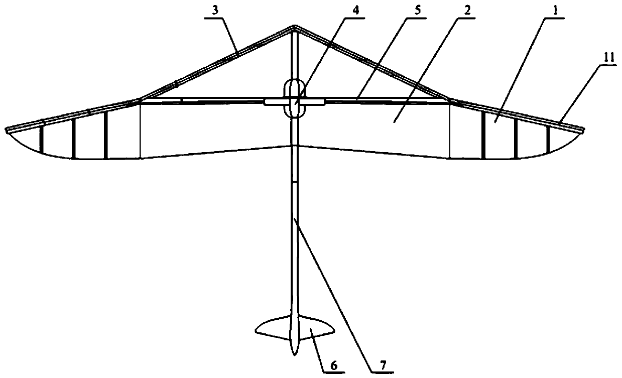
The invention discloses a flapping mechanism of a composite aircraft. The flapping mechanism comprises a rack, an airfoil, a transmission module, a flapping wing locking module and an empennage. The fixed wing-flapping wing composite layout is adopted, and the flapping wing surface is small, so that the aerodynamic load and vibration borne by the structure are small, and the design strength and rigidity requirements can also be met for a large aircraft. Due to the existence of the fixed wing sections, compared with a traditional flapping wing aircraft, the aircraft is smaller in lifting thrustchange amplitude, and therefore the aircraft is smaller in shaking amplitude and better in comfort in the flying process. The flapping mechanism can be locked into a fixed wing mode in the gliding stage of the aircraft, the aerodynamic efficiency of the aircraft is improved, the voyage and endurance are prolonged, and more stable lift force can be achieved in the fixed wing mode. And meanwhile, the aerodynamic noise in the flight process is greatly reduced.

Description

technical field [0001] The invention belongs to the technical field of aircraft, and in particular relates to a composite aircraft, in particular to a flapping mechanism of the composite aircraft. Background technique [0002] Most of the existing compound aircrafts adopt the combination of fixed wing and rotor, and the rotor generates forward thrust. However, the large aerodynamic noise generated during the rotor motion is poor in concealment and may cause serious noise pollution. [0003] Existing studies on flapping-wing aircraft are almost all focused on small and medium-sized flapping-wing aircraft, and there is not much research on the mechanism design of large-scale flapping-wing aircraft. The fixed-wing-flapping-wing composite layout of the aircraft, the fixed-wing wing section always produces a relatively stable lift during flight, and the left and right flapping wings flutter up and down to generate periodic lift and sufficient forward thrust. [0004] Due to the...

Claims


Application Information

Patent Timeline
IPC IPC(8): B64C33/02
CPCB64C33/02
Inventor 李道春李华东邵浩原孙毅张尧王子瑜向锦武
Owner BEIHANG UNIV
Learn More