Energy-optimized aircraft electromechanical system thermal management method

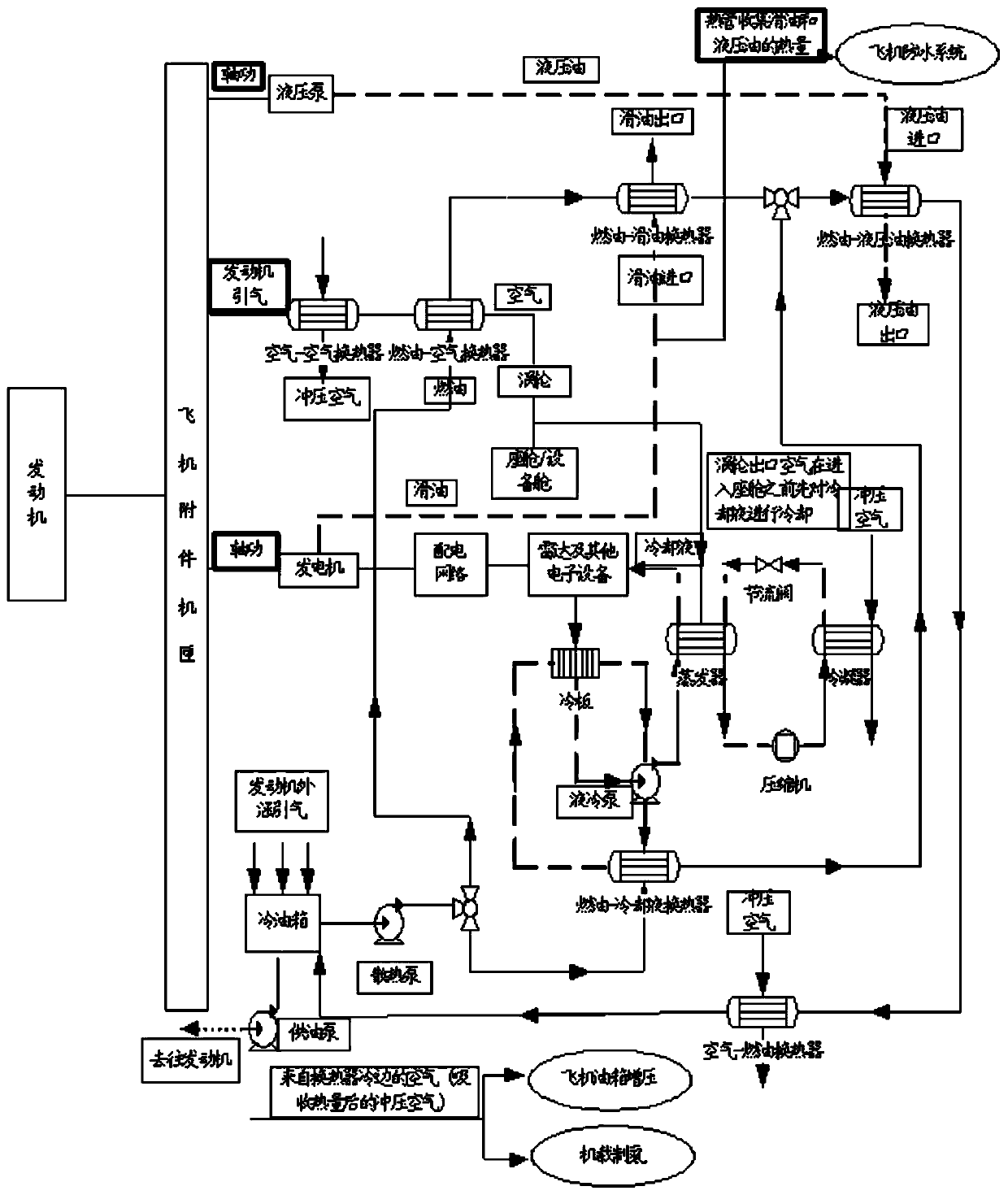
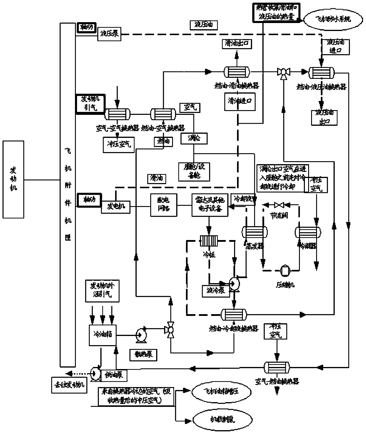
An electromechanical system and energy optimization technology, which is applied in the field of aircraft thermal management, can solve problems such as restrictions and lower fuel heat dissipation levels, and achieve the effects of reducing bleed air volume, improving heat sink capacity, and lowering temperature

Active Publication Date: 2020-04-17
SHENYANG AIRCRAFT DESIGN INST AVIATION IND CORP OF CHINA
View PDF9 Cites 14 Cited by
  • Summary
  • Abstract
  • Description
  • Claims
  • Application Information

AI Technical Summary

Problems solved by technology

The main cooling sources for dissipating heat from the aircraft include fuel oil and ram air, but the heat sink capabilities of these two types of cooling sources on the aircraft are currently restricted to varying degrees: on the one hand, the use of aircraft composite materials reduces the fuel flow through the fuel tank structure. The level of heat dissipation to the outside world; on the other hand, the high stealth requirements of the aircraft limit the flow of ram air introduced from the outside

Method used


Image

  • Energy-optimized aircraft electromechanical system thermal management method
  • Energy-optimized aircraft electromechanical system thermal management method

Examples


Embodiment Construction

[0022] In order to make the objectives, technical solutions and advantages of the implementation of the application clearer, the technical solutions in the implementation modes of the application will be described in more detail below with reference to the drawings in the implementation modes of the application. In the drawings, the same or similar reference numerals denote the same or similar elements or elements having the same or similar functions throughout. The described embodiments are some, but not all, embodiments of the present application. The embodiments described below by referring to the figures are exemplary and are intended to explain the present application, and should not be construed as limiting the present application. Based on the implementation manners in this application, all other implementation manners obtained by persons of ordinary skill in the art without creative efforts fall within the scope of protection of this application. Embodiments of the pr...


PUM


Abstract

The invention belongs to the technical field of aircraft thermal management, and relates to an energy-optimized aircraft electromechanical system thermal management method. The method comprises the steps: introducing a part of ram air absorbing heat of a heat source into a fuel tank and airborne nitrogen making equipment through a first pipeline to serve as a fuel tank pressurization air source and an airborne nitrogen making supplementary air source; leading out air from the rear end of the engine outer culvert fan to serve as a cold source to be led into the cold fuel tank heat exchanger, and soaking the cold oil tank heat exchanger in fuel oil of the fuel tank. The use mode of ram air is optimized, the air source serves as an air source of an oil tank pressurization and airborne nitrogen generation system, the air entraining amount of the engine is effectively reduced, the cold fuel tank is designed, air is led out from the rear portion of an outer culvert fan of the engine to serveas a cold source, fuel oil is cooled, the temperature of the fuel oil is reduced, and the heat sink capacity of the fuel oil is improved.

Description

technical field [0001] The application belongs to the technical field of aircraft thermal management, and in particular relates to an energy-optimized thermal management method of an aircraft electromechanical system. Background technique [0002] The aircraft electromechanical system is one of the largest airborne systems with the most complex structure and functions on the aircraft. It is composed of multiple subsystems such as hydraulic pressure, fuel oil and environmental control. [0003] At present, the development trend of each subsystem of the electromechanical system has obvious independence, that is, each subsystem develops independently. Although the cross-linking and interface relationship between each other has been determined in the design of the system scheme, it has not been integrated and developed as an organic whole. / Optimized use of energy and comprehensive regulation. In addition, the heat dissipation and energy requirements of the system are basicall...

Claims


Application Information

Patent Timeline
Patent Type & Authority Applications(China)
IPC IPC(8): B64D37/34B64D37/32B64D13/08B64D15/02H05K7/20
CPCB64D13/08B64D15/02B64D37/32B64D37/34H05K7/20845H05K7/20945
Inventor 王亚盟李征鸿刘亮亮丁磊刘静
Owner SHENYANG AIRCRAFT DESIGN INST AVIATION IND CORP OF CHINA
Why Eureka
Try Eureka