
Method for paving stone slabs

A stone slab and pavement technology, applied in the field of garden engineering, can solve problems such as integration into green belts, difficulty in stone slabs, difficulty in meeting the requirements of stone slab paving methods, etc., to achieve the effect of strengthening greening and easy survival

Active Publication Date: 2021-08-10
CHENGTONG KAISHENG ECOLOGICAL CONSTR CO LTD
View PDF0 Cites 0 Cited by
  • Summary
  • Abstract
  • Description
  • Claims
  • Application Information

AI Technical Summary

Problems solved by technology

[0004] The existing technical solutions above have the following defects: the separation of the stone slabs from the green belt is relatively abrupt, and the stone slabs are difficult to integrate into the green belts; with the continuous improvement of modern people's requirements for greening, the existing stone slab paving methods are difficult to meet Require

Method used


Image

  • Method for paving stone slabs
  • Method for paving stone slabs
  • Method for paving stone slabs

Examples


Embodiment 1

[0042] A method for paving a stone slab, comprising the following steps:

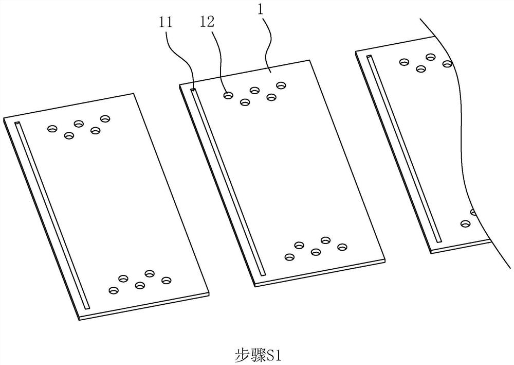
[0043] Step S1: Refer to figure 1 , a plurality of backing plates 1 are laid on the land, and the backing plate 1 is a strip-shaped rectangular plate, and its length is more than twice the width. Preferably it is 0.8~1cm. The top surface of the backing plate 1 is provided with an abutting groove 11 , the length direction of the abutting groove 11 is along the length direction of the backing plate 1 , and the abutting groove 11 is close to a sidewall of one long side of the backing plate 1 .

[0044] The material of the backing plate 1 is the same as that of the permeable brick. The backing plate 1 has numerous air-permeable and water-permeable micropores. The backing plate 1 is directly produced by the same process as the permeable brick, and will not be described here. A plurality of planting holes 12 are formed through the surface of the backing plate 1 , and the planting holes 12 are located near b...

Embodiment 2

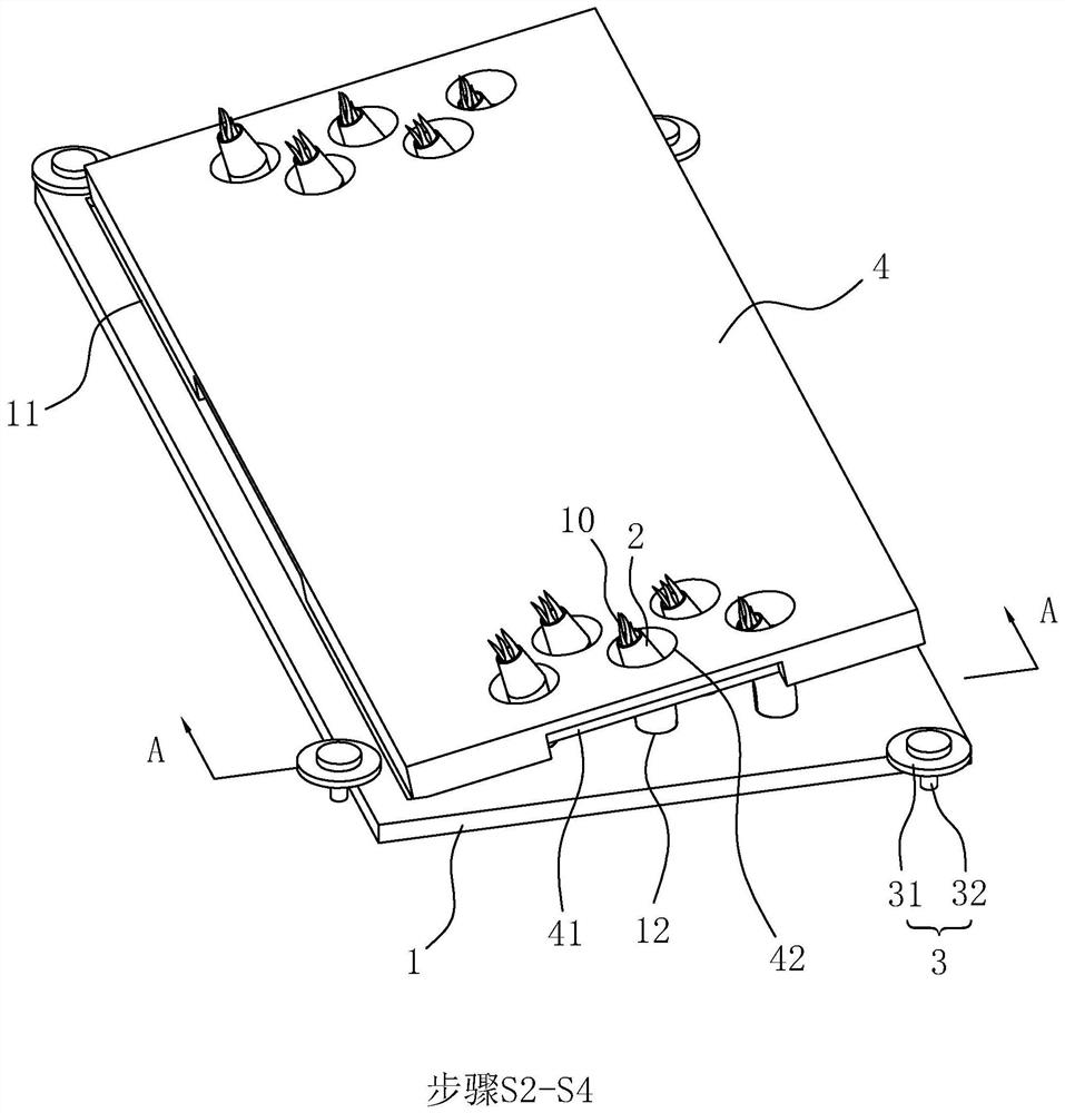
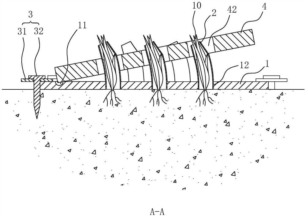
[0056] refer to Image 6 , a pavement method for stone slabs, the difference between the second embodiment and the first embodiment is that the planting holes 12 are distributed at various positions on the surface of the backing plate 1, and the through holes 42 are also distributed at various positions on the surface of the stone slab 4, The plant 10 is selected from a variety with a relatively low height. After the plant 10 is fully grown, the top of the plant 10 does not protrude from the through hole 42 .

[0057] Through the paving method of this embodiment, pedestrians can step on any position on the stone slab 4 without damaging the plants 10 . The plants 10 located in the through holes 42 can be seen by people, and the plants 10 also appear to grow out of the slate 4 . The effect of the integration of the slate 4 and the plants 10 is better, further strengthening the greening effect.


PUM


Abstract

The invention discloses a method for laying stone slabs, which relates to gardening engineering. The key points of the technical solution are as follows: step S1: laying a plurality of backing boards on the ground, and the position of the backing boards is laid in the direction of the road , the plate surface of the backing plate is provided with a plurality of planting holes; step S2: plant plants in the planting holes, and maintain the plants to make them survive; step S3: take the casing and insert it into the planting hole, put the casing outside the plant, The upper end of the tube protrudes from the top surface of the backing plate; step S4: take the stone plate and cover it on the backing plate, and the stone plate is provided with through holes corresponding to the planting holes one by one; in the process of stacking the stone plates, make the casing pass through each through hole ; Step S5: pulling out the casing to complete the laying. Through this laying method, the plants appear as a posture growing from the stone slabs, and the stone slabs and plants can be integrated, which further strengthens the greening effect and meets the needs of modern people; this laying method is not easy to crush the plants during construction, and the plants are placed on the backing plate. , It is easy to survive in the stone slab.

Description

technical field [0001] The invention relates to garden engineering, in particular to a stone board paving method. Background technique [0002] In municipal garden projects, in order to meet both greening and pedestrian traffic, it is often necessary to lay stone slabs on the green belt, the stone slabs are laid to form roads, and the stone slabs are used as footholds for pedestrians to step on. [0003] The existing method of laying stone slabs is as follows: select a location on the green belt, transport the stone slabs to a predetermined position and put them down; the stone slabs are laid at intervals or continuously along the direction of the path to form a road. The stone slab has a large self-weight. After the stone slab is laid, it is stable enough and will not move during normal use. [0004] The existing technical solutions above have the following defects: the separation of the stone slabs from the green belt is relatively abrupt, and the stone slabs are difficul...

Claims


Application Information

Patent Timeline
Patent Type & Authority Patents(China)
IPC IPC(8): E01C15/00E01C5/02A01G9/02
CPCA01G9/02E01C5/02E01C15/00
Inventor 陈智勇郭继成陆孝英赵维锋
Owner CHENGTONG KAISHENG ECOLOGICAL CONSTR CO LTD
Learn More