Piston device with speed response mechanism

A technology with speed and piston, which is applied in the direction of fuel control, charging system and engine components of turbine/propulsion device, which can solve problems such as unfavorable engine ignition, sudden change of fuel supply, rich oil flameout, etc., and achieve the goal of improving the success rate of ignition Effect

Active Publication Date: 2020-04-17
XIAN AERO ENGINE CONTROLS
View PDF4 Cites 1 Cited by
  • Summary
  • Abstract
  • Description
  • Claims
  • Application Information

AI Technical Summary

Problems solved by technology

[0002] The valve of prior art (the structural representation of adopted piston is as figure 1 shown) in normal operation, the piston is controlled by the fuel pressure difference between the left and right chambers (the structural diagram is shown in figure 1 shown) to control the opening and closing of the oil circuit, and quickly stop against the mating surface of the matching components, which will inevitably cause a sudden change in the opening of the valve, resulting in a sudden change in fuel supply, which is not conducive to the ignition of the engine, resulting in fuel-rich flameout Phenomenon

Method used


Image

  • Piston device with speed response mechanism
  • Piston device with speed response mechanism
  • Piston device with speed response mechanism

Examples


Embodiment Construction

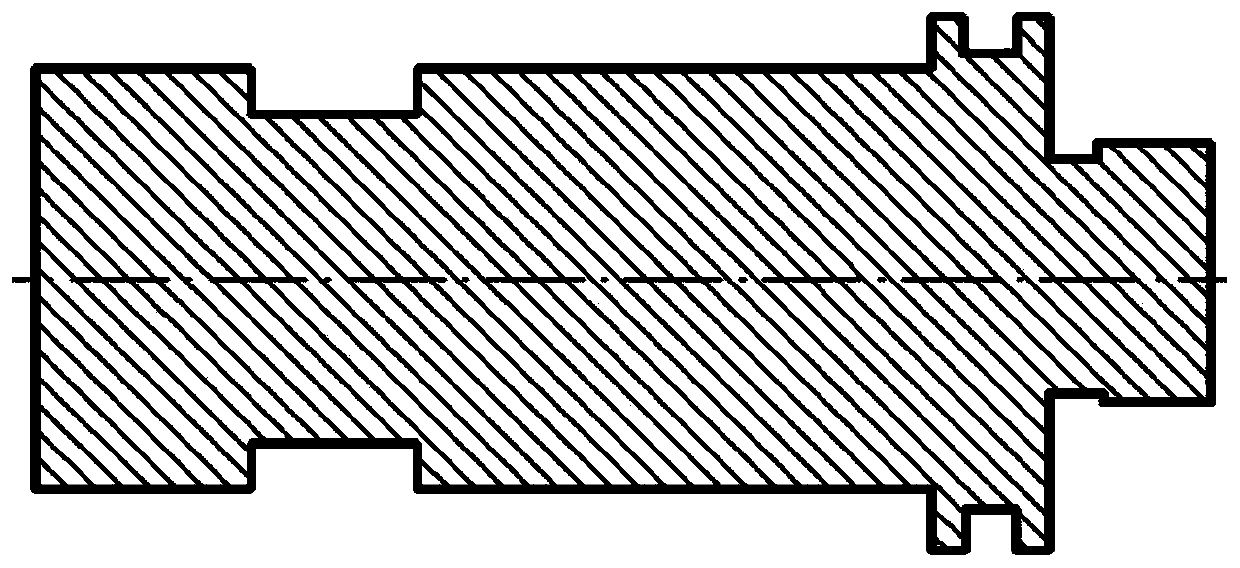
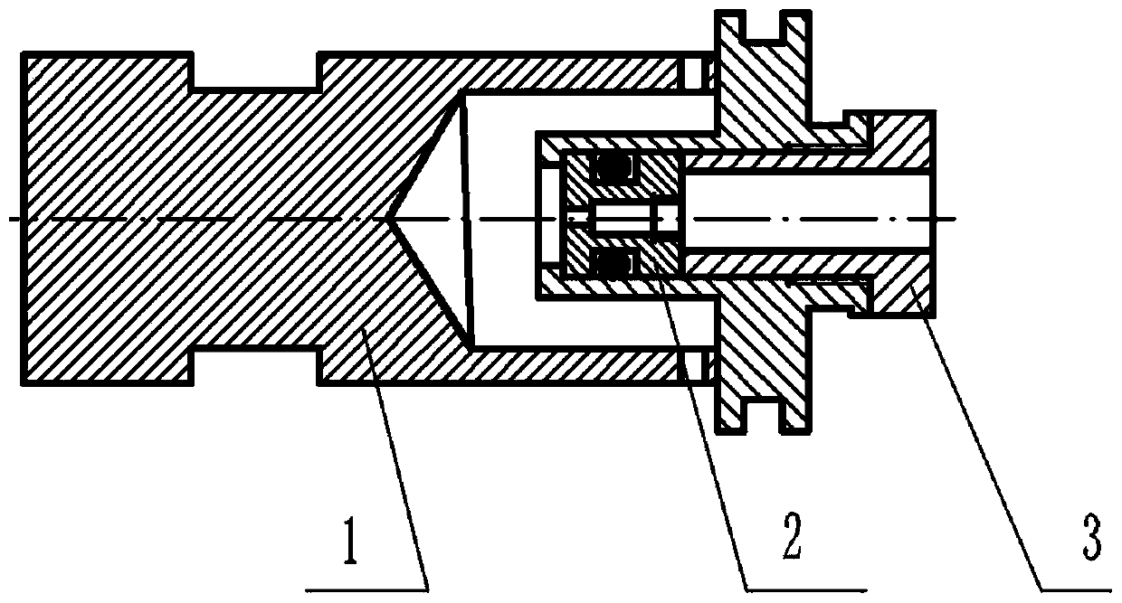
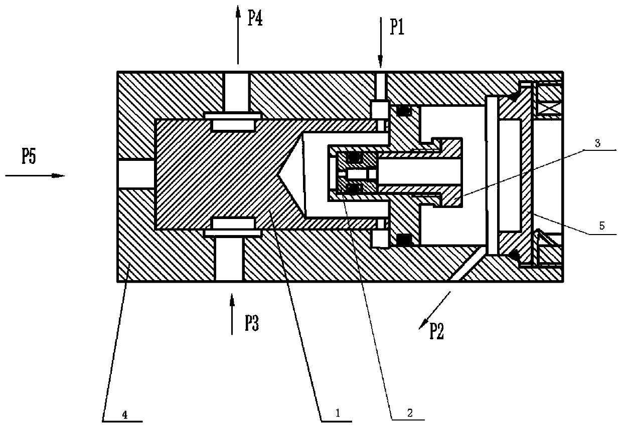
[0019] see image 3 The present invention provides a piston device with a speed response mechanism, which includes a housing 4 and a piston placed inside the housing 4 that can move along the axial direction of the housing 4. The housing 4 is provided with a working oil passage inlet P3 and The outlet of the working oil circuit is P4, and the piston is provided with a ring-shaped working oil circuit channel; the piston includes a piston head 1 and a flow-adjustable piston seat fixedly connected to the piston head 1; the housing 4 is provided with a regulating oil circuit inlet P1 and regulating oil The outlet P2 of the regulating oil circuit; the inlet P1 of the regulating oil circuit communicates with the outlet P2 of the regulating oil circuit through the flow-adjustable piston seat; Move along the axial direction of the housing 4, and when it reaches the predetermined position of the housing 4, the inlet P3 of the working oil circuit communicates with the outlet P4 of the w...


PUM


Abstract

The invention belongs to the field of aero-engine fuel oil systems, and relates to a piston device with a speed response mechanism. The piston device comprises a shell and a piston mounted in the shell, the shell is provided with a work oil path inlet and a work oil path outlet, the piston is provided with an annular work oil path channel, the piston comprises a piston head and a flow adjusting type piston base fixedly connected with the piston head, an adjusting oil path inlet and an adjusting oil path outlet are formed in the shell, the adjusting oil path inlet communicates with the adjusting oil path outlet through the flow adjusting type piston base, when the adjusting oil path outlet is closed, the piston head can move in the shell in the axial direction of the shell, the work oil path inlet communicates with the work oil path outlet through an annular work oil path channel, when the adjusting oil path outlet is opened, the piston head moves in the shell in the axial direction ofthe shell, and the work oil path inlet and the work oil path outlet are disconnected. The oil supply rate of a product during the ignition period can be ensured, and after ignition, normal work is achieved.

Description

technical field [0001] The invention belongs to the field of aero-engine fuel systems, and relates to a piston device with a speed response mechanism, in particular to a piston device with a speed response mechanism for controlling connection of a combustion chamber in an aero-engine fuel system. Background technique [0002] The valve of prior art (the structural representation of adopted piston is as figure 1 shown) in normal operation, the piston is controlled by the fuel pressure difference between the left and right chambers (the structural diagram is shown in figure 1 shown) to control the opening and closing of the oil circuit, and quickly stop against the mating surface of the matching components, which will inevitably cause a sudden change in the opening of the valve, resulting in a sudden change in fuel supply, which is not conducive to the ignition of the engine, resulting in fuel-rich flameout Phenomenon. Contents of the invention [0003] In order to solve t...

Claims


Application Information

Patent Timeline
IPC IPC(8): F02C7/22F02C9/26F02C9/32
CPCF02C7/22F02C9/26F02C9/32
Inventor 赵继平王润宗张文学孙琦赵静云
Owner XIAN AERO ENGINE CONTROLS
Why Eureka
Try Eureka