An inertial adjustable low frequency vibration isolation device

A vibration isolation, low frequency technology, applied in the field of inertial adjustable low frequency vibration isolation devices, can solve the problems of inconvenient adjustment of the quality of the shock absorption system, and the inability of the shock absorption system to effectively suppress the low frequency vibration, so as to reduce the influence of basic vibration and reduce the Effect of resonance frequency, low resonance frequency

Active Publication Date: 2021-06-18
HARBIN ENG UNIV
View PDF7 Cites 0 Cited by
  • Summary
  • Abstract
  • Description
  • Claims
  • Application Information

AI Technical Summary

Problems solved by technology

[0003] In order to solve the problem that the traditional damping system cannot effectively suppress low-frequency vibrations, and it is very inconvenient to adjust the quality of the damping system, which is not conducive to producing effective damping effects on different frequency bands, the present invention further provides an inertial Lower frequency vibration isolation device

Method used


Image

  • An inertial adjustable low frequency vibration isolation device
  • An inertial adjustable low frequency vibration isolation device
  • An inertial adjustable low frequency vibration isolation device

Examples


specific Embodiment approach 1

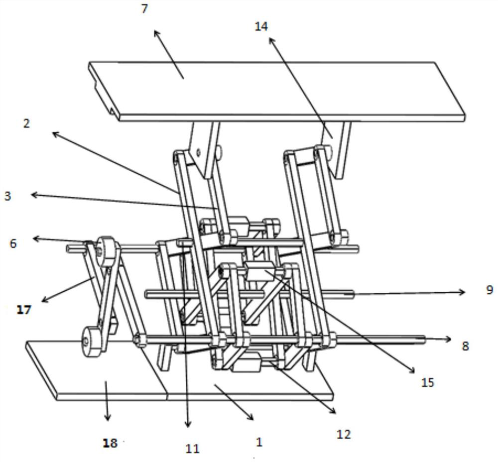
[0026] Specific implementation mode one: refer to Figure 1 to Figure 5 Describe this embodiment. This embodiment provides an inertial adjustable low-frequency vibration isolation device. The vibration isolation device includes a base 1, a supporting plate 7, a shock absorbing mechanism, and a counterweight mechanism. Relatively arranged, the supporting mechanism is arranged between the base 1 and the supporting plate 7, and one end of the supporting mechanism is fixedly connected with the base 1, the other end of the supporting mechanism is fixedly connected with the supporting plate 7, and the shock absorbing mechanism is arranged inside the supporting mechanism, and The damping mechanism is fixedly connected with the support mechanism, the counterweight mechanism is arranged on one side of the support mechanism, and the counterweight mechanism is fixedly connected with the support mechanism.

[0027] In this embodiment, the base 1 and the supporting mechanism mainly play a ...

specific Embodiment approach 2

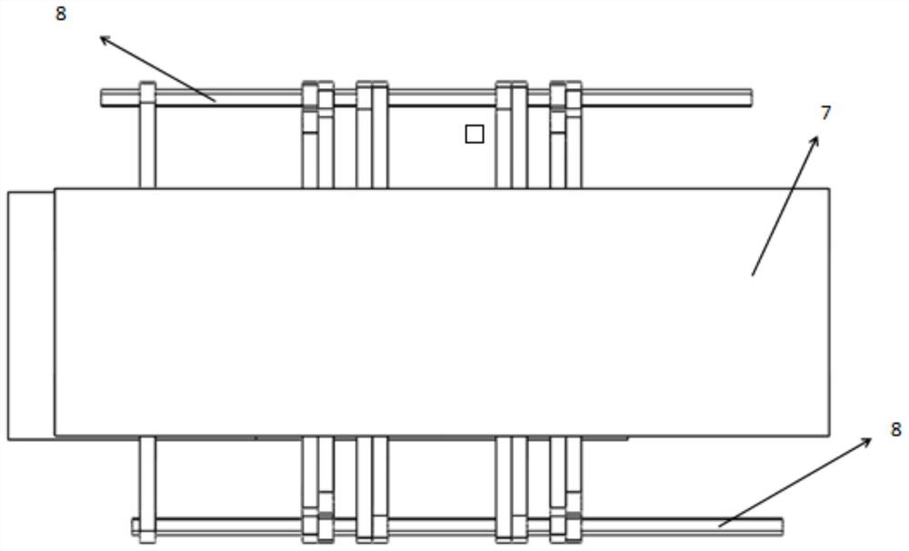
[0028] Specific implementation mode two: refer to Figure 1 to Figure 5Describe this embodiment, this embodiment is to further limit the support mechanism described in the first embodiment, in this embodiment, the support mechanism includes the third cylindrical connecting rod 10, the fourth cylindrical connecting rod 11, two one No. cylindrical connecting rod 8, two L-shaped rigid plates 14, two rigid support plates 16 and two supporting trusses, the supporting trusses are "8"-shaped frames, and the two supporting trusses pass through No. 3 cylindrical connecting rods 10 , No. 4 cylindrical connecting rod 11 is connected with two No. 1 cylindrical connecting rods 8, No. 4 cylindrical connecting rod 11 is set at the center of two supporting trusses, and the two ends of No. 3 cylindrical connecting rod 10 respectively pass through a supporting truss and connect with it Rotationally connected, the two No. 1 cylindrical connecting rods 8 are all arranged on the lower part of the ...

specific Embodiment approach 3

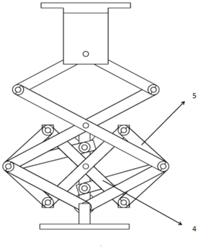
[0030] Specific implementation mode three: refer to Figure 1 to Figure 5 Describe this embodiment, this embodiment is to further limit the support truss in the second specific embodiment, in this embodiment, the support truss includes two No. 1 three-hole long rods 2 and four No. 1 two-hole short rods 3. Two No. 1 three-hole long rods 2 are arranged in an X shape, and two No. 1 three-hole long rods 2 are hinged, and two No. 1 two-hole short rods 3 of the four No. 1 two-hole short rods 3 are set on Above the two No. 1 three-hole long rods 2, one end of the No. 1 two-hole short rod 3 in the two No. 1 two-hole short rods 3 is hinged with one end of the other two-hole short rod 3, and two No. 1 two-hole short rods 3 are hinged. The other end of each No. 1 two-hole short rod 3 in the short rod 3 is hinged with one end of a No. 1 three-hole long rod 2, and the other two No. 1 two-hole short rods in the four No. 1 two-hole short rods 3 are hinged. 3 is arranged below the two No. 1 ...


PUM


Abstract

An inertial adjustable low-frequency vibration isolation device belongs to the field of engineering vibration isolation. The invention aims to solve the problem that the traditional damping system cannot effectively suppress low-frequency vibrations, and it is very inconvenient to adjust the quality of the damping system, which is not conducive to different The frequency band produces effective vibration reduction effect. The vibration isolation device of the present invention includes a base, a supporting plate, a supporting mechanism, a shock absorbing mechanism and a counterweight mechanism. Between the supporting plates, one end of the supporting mechanism is fixedly connected to the base, the other end of the supporting mechanism is fixedly connected to the supporting plate, the shock absorbing mechanism is arranged inside the supporting mechanism, and the shock absorbing mechanism is fixedly connected to the supporting mechanism, and the counterweight mechanism is set It is on one side of the supporting mechanism, and the counterweight mechanism is fixedly connected with the supporting mechanism. The invention is mainly applied to low-frequency vibration isolation treatment in the field of engineering manufacturing.

Description

technical field [0001] The invention belongs to the field of engineering vibration isolation, and in particular relates to an inertia-adjustable low-frequency vibration isolation device. Background technique [0002] Vibrating systems are often encountered in scientific technology and engineering research, and a vibration isolation problem exists in most engineering practices. In practical life, the human body is an extremely good vibration isolation structure. In this study, a novel passive body-excited anti-vibration structure with nonlinear inertial coupling (HBIAVS-NI) is used for its advanced vibration isolation. Use bionics to make a system including exoskeleton and inner muscles, and perform vibration isolation treatment for low-frequency vibrations whose main frequencies are generally concentrated in the low-frequency band. This kind of microvibration will have a greater impact on the confidential devices inside the structure. Therefore, the design of the low-frequ...

Claims


Application Information

Patent Timeline
Patent Type & Authority Patents(China)
IPC IPC(8): F16F15/02F16F15/04F16F15/28
CPCF16F15/02F16F15/04F16F15/28
Inventor 刘春川樊创碧王喆
Owner HARBIN ENG UNIV
Why Eureka
Try Eureka