Differential gear connecting structure
A gear connection and differential technology, applied in the field of auto parts, can solve the problems of low gear precision, limited torque transmission capacity, increased bolts, etc., and achieve the effect of reducing weight, improving torque transmission capacity, and reducing processes
- Summary
- Abstract
- Description
- Claims
- Application Information
AI Technical Summary
Problems solved by technology
Method used
Image

Examples
Embodiment 1
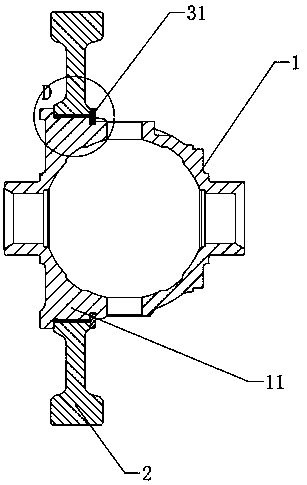
[0031] Example 1, please refer to Figure 1~2 , the present invention provides a differential gear connection structure, including a differential case 1 and a driven gear 2, the differential case 1 is provided with an assembly shaft section 11 for assembling the driven gear 2, The driven gear 2 is assembled on the assembly shaft section 11, and the assembly shaft section 11 and the driven gear 2 are connected through a spline 4, and the spline 4 connection is adopted, and then the teeth are ground after heat, and finally The design accuracy of the driven gear 2 is greatly improved, the NVH performance is improved, the process and parts are greatly reduced, the cost is reduced, and the weight is also reduced. The use of spline 4 coupling can also greatly improve the ability to transmit torque. The assembly shaft section 11 is provided with an external spline 4, the inner hole of the driven gear 2 is provided with an internal spline 4, the internal spline 4 and the external spl...
Embodiment 2
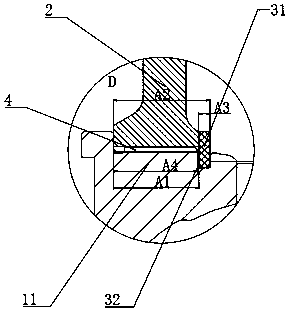
[0034] Example 2, please refer to Figure 3~4 A first inclined surface 33 is provided on the side of the locking groove 32 away from the step, and a second inclined surface having the same angle as the first inclined surface 33 is arranged on a position corresponding to the first inclined surface 33 of the locking groove 32 . Corresponding first slope 33 and second slope are set on the slot 32 and the collar 31, so that the collar 31 has a self-locking function, no pad selection is required, and the friction self-locking principle of the slope is used to prevent falling off. There is a slope, and the collar is reasonably designed to realize the limit of the collar without backlash. At the same time, due to the clamping force of the snap ring, the axial gap F of the driven gear 2 can be effectively eliminated to control the axial size of the driven gear 2, and the axial transmission of the driven gear 2 can be effectively controlled and prevented, and the driven gear 2 can be e...
Embodiment 3
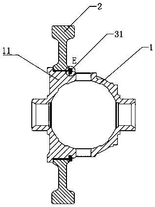
[0036] Embodiment three, please refer to Figure 5~6 , the stopper is a pin shaft 34, and the spline 4 adopts an interference design and a pin limit method to limit the axial width to improve safety, and the end of the assembly shaft section 11 away from the step is provided with a pin for installation The installation hole of the shaft 34, the interference fit between the pin shaft 34 and the installation hole, so that the interference fit between the pin shaft 34 and the installation hole prevents the pin shaft 34 from falling off during the rotation process, and the installation hole is arranged on the circumference of the assembly shaft section 11 face. The stopper is provided with the pin shaft 34, which can be completed by only drilling a small amount of mounting holes on the assembly shaft section 11, and the installation of the pin shaft 34 is simple and convenient.
[0037] As a further improvement to the above technical solution, at least two pin shafts 34 are provi...
PUM
 Abstract
Description
Claims
Application Information
 - R&D
- Intellectual Property
- Life Sciences
- Materials
- Tech Scout
- Unparalleled Data Quality
- Higher Quality Content
- 60% Fewer Hallucinations
Browse by: Latest US Patents, China's latest patents, Technical Efficacy Thesaurus, Application Domain, Technology Topic, Popular Technical Reports.
© 2025 PatSnap. All rights reserved.Legal|Privacy policy|Modern Slavery Act Transparency Statement|Sitemap|About US| Contact US: help@patsnap.com