Pipe reinforcement connection device for sewer system

A technology for connecting devices and sewers, which is applied in the directions of pipe supports, sleeve/socket connections, pipes/pipe joints/pipes, etc. It can solve the problems of inability to install, seal and disassemble pipes, and achieve the effect of reducing excavation works and convenient operation.

Active Publication Date: 2021-06-25
王姝娟
View PDF6 Cites 0 Cited by
  • Summary
  • Abstract
  • Description
  • Claims
  • Application Information

AI Technical Summary

Problems solved by technology

However, this equipment cannot effectively and quickly install, connect, seal and disassemble the pipes in the sewer

Method used


Image

  • Pipe reinforcement connection device for sewer system
  • Pipe reinforcement connection device for sewer system
  • Pipe reinforcement connection device for sewer system

Examples


specific Embodiment approach 1

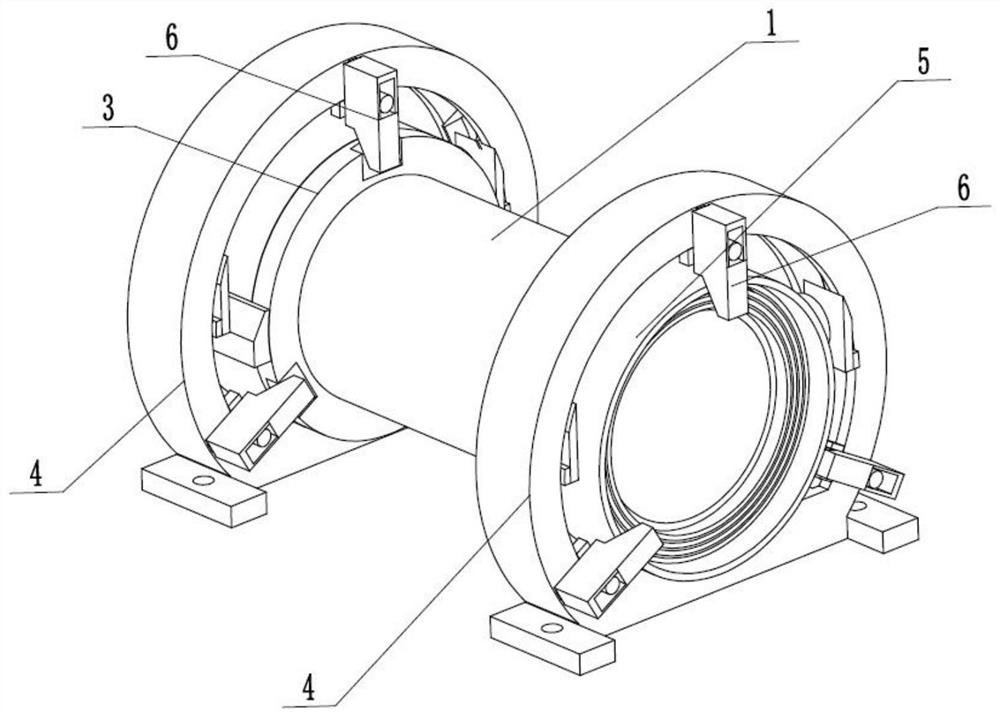
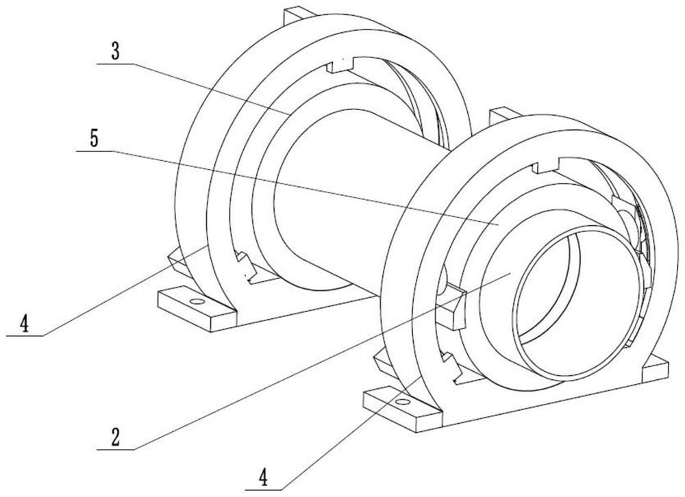
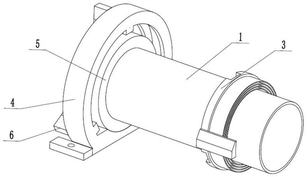
[0031] like Figure 1 to Figure 12As shown, a pipe reinforcement connection device for a sewer system, including a joint pipe 1, a fixed pipe 2, a joint seal socket 3, a fixed support seal base 4, a fixed seal socket 5 and an adjustment locking fixture 6, the described The joint seal socket 3 is fixedly connected to the inner end of the joint pipe 1, the joint seal socket 3 is plugged and sealed in the fixed support seal base 4, the fixed support seal base 4 is fixedly connected to the outer end of the fixed connection fixed pipe 2, and the fixed support seal base 4 is fixedly connected to the fixed sealing socket 5, and the adjusting locking fixer 6 is slidably connected in the fixed sealing socket 5, and the adjusting locking fixing device 6 is meshed with the joint sealing socket 3 for transmission, and the adjusting locking fixing device 6 is closely fitted to the plug Connected in the connecting sealing socket 3. The fixed support sealing base 4 is fixed by anchor bolts,...

specific Embodiment approach 2

[0033] like Figure 1 to Figure 12 As shown, this embodiment further describes the first embodiment, the joint sealing socket 3 includes a fixed outer ring seat 3-1, three slope slots 3-2, two tapered racks 3-3 and a plurality of The sealing plate 3-4, the fixed outer ring seat 3-1 is fixedly connected to the inner end of the outer wall of the connecting pipe 1, and the outer wall of the fixed outer ring seat 3-1 is uniformly provided with three slope slots 3-2, two tapered The racks 3-3 are respectively fixedly connected to the two ends of the fixed outer ring seat 3-1, and the inner ends of the fixed outer ring seat 3-1 are evenly and fixedly connected to a plurality of sealing plates 3-4.

specific Embodiment approach 3

[0035] like Figure 1 to Figure 12 As shown, this embodiment further explains the second embodiment, the fixed support seal base 4 includes a fixed ring seat 4-1, two anchor anchor seats 4-2, two anchor threaded holes 4-3 , inner ring rack sliding groove 4-4, rack slider sliding groove 4-5, three T-shaped chute 4-6 and three rotating circular holes 4-7, fixed ring seat 4-1 lower end The two sides are respectively fixedly connected with two anchor holders 4-2, the anchor holder 4-2 is provided with an anchor threaded hole 4-3, and the inner ring rack sliding groove 4-4 is arranged on the fixed ring seat 4 In -1, the two ends of the inner wall of the inner ring rack sliding groove 4-4 are provided with a rack slider sliding groove 4-5, and the outer end of the fixed ring seat 4-1 is evenly provided with three T-shaped sliding grooves 4- 6. The outer end of the fixed ring seat 4-1 is evenly arranged, and the rotating circular hole 4-7 is arranged on the lower side of the T-shape...


PUM


Abstract

The present invention relates to the field of sewer systems, more specifically, a pipe reinforcement connection device for sewer systems, including connecting pipes, fixed pipes, connecting sealing sockets, fixed support sealing bases, fixed sealing sockets and adjusting locking fixtures, The joint seal socket is fixedly connected to the inner end of the joint pipe, the joint seal socket is plugged and sealed in the fixed support seal base, the fixed support seal base is fixedly connected to the outer end of the fixed tube, and the fixed support seal base is fixedly connected to the On the fixed sealing socket, the adjusting and locking fixer is slidably connected in the fixed sealing socket; the beneficial effect of the present invention is to quickly and effectively install, connect, fix and seal the pipelines of the underground sewer system; reduce large-scale excavation Engineering, the nearby pipeline can be quickly disassembled and replaced through the sewer channel; it is easy to operate and convenient for actual use.

Description

technical field [0001] The invention relates to the field of sewer systems, in particular to a pipe reinforcement connection device for the sewer system. Background technique [0002] Patent No. CN201510576355.X discloses a high-temperature, high-pressure large-diameter pipe fixing bracket, which includes the following parts: a bracket frame with legs at the bottom, and a limit hole on the frame; a force transmission limit ring beam, which is sleeved between the bracket frame and the pipeline On the pipe wall between the two ends, there are concave slopes for contact with the longitudinal force-transmitting limit stiffener; the force-transmitting corbel; On the outer wall surface of the pipeline on the front and rear sides of the position ring beam, the side close to the contact of the force transmission limit ring beam is wedge-shaped, which cooperates with the concave slope of the force transmission limit ring beam to form a friction surface for relative displacement up an...

Claims


Application Information

Patent Timeline
Patent Type & Authority Patents(China)
IPC IPC(8): F16L3/08F16L21/02F16L21/08
CPCF16L3/08F16L21/02F16L21/08
Inventor 王姝娟
Owner 王姝娟
Why Eureka
Try Eureka