Supercharge Your Innovation With Domain-Expert AI Agents!

Radar antenna azimuth rotary table

A radar antenna, azimuth technology, applied in the field of radar

Inactive Publication Date: 2020-04-17
WUHU LE CHUANG ELECTRONICS TECH CO LTD
View PDF0 Cites 1 Cited by
  • Summary
  • Abstract
  • Description
  • Claims
  • Application Information

AI Technical Summary

Problems solved by technology

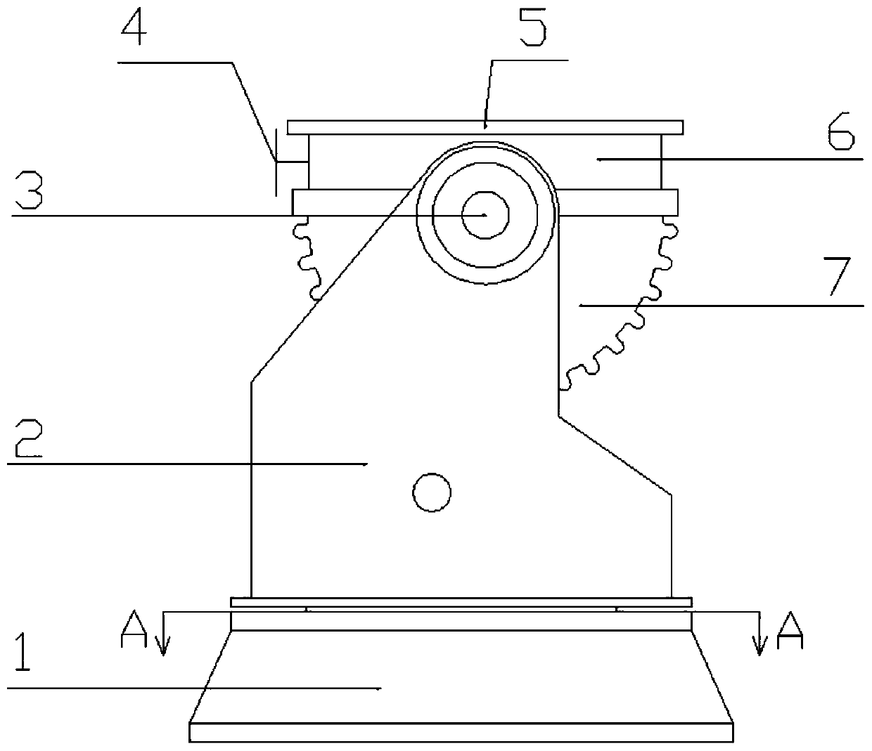
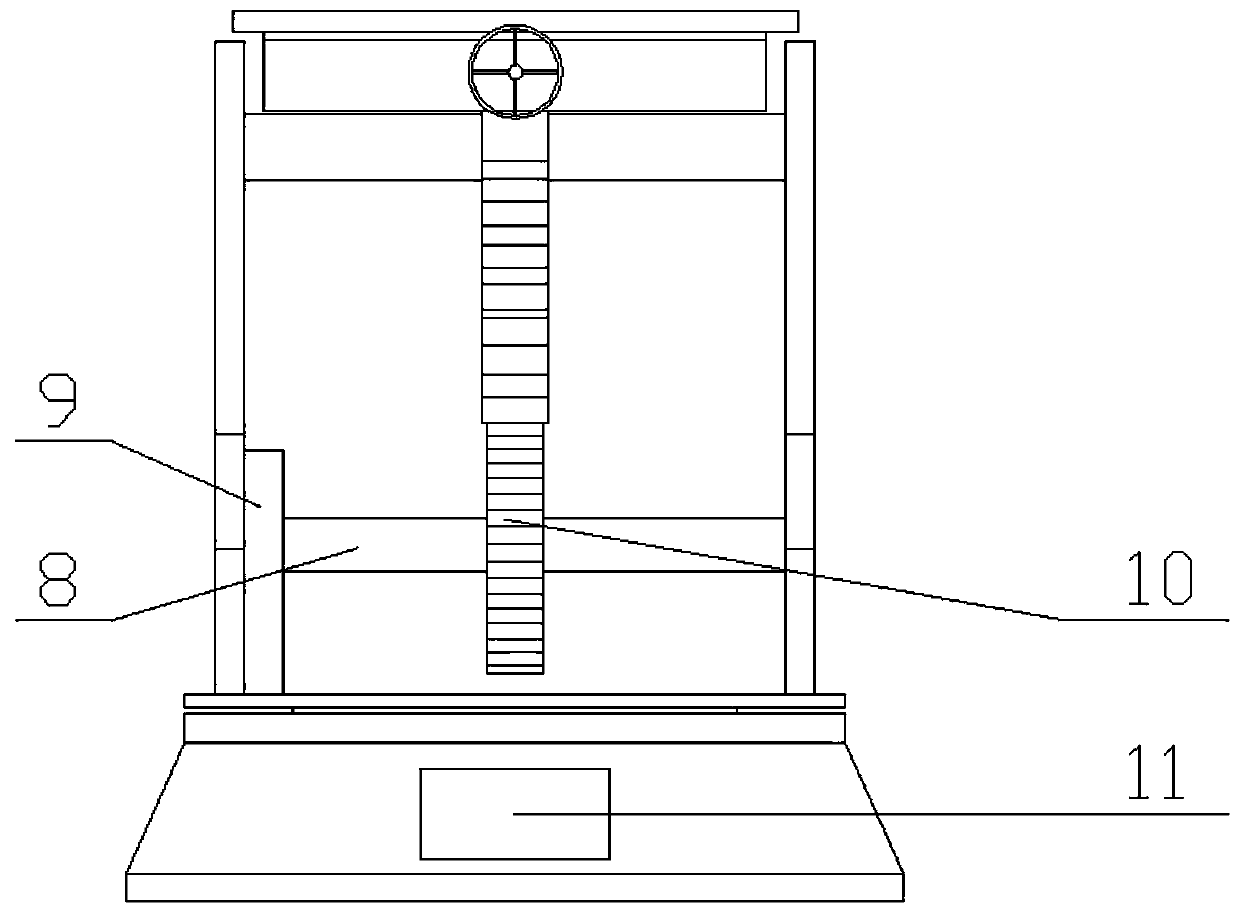
[0003] The purpose of the present invention is to provide a radar antenna azimuth turntable for testing, which solves the problems in the adjustment of the azimuth angle and pitch angle of the existing antenna test by setting the upper azimuth turntable, the middle pitch mechanism, and the lower azimuth turntable

Method used


Image

  • Radar antenna azimuth rotary table
  • Radar antenna azimuth rotary table
  • Radar antenna azimuth rotary table

Examples


Embodiment Construction

[0030] The technical solutions in the embodiments of the present invention will be clearly and completely described below in conjunction with the accompanying drawings in the embodiments of the present invention. Obviously, the described embodiments are only a part of the embodiments of the present invention, rather than all the embodiments. Based on the embodiments of the present invention, all other embodiments obtained by those of ordinary skill in the art without creative work shall fall within the protection scope of the present invention.

[0031] In the description of the present invention, it should be understood that the terms "opening", "upper", "lower", "thickness", "top", "middle", "length", "inner", "around", etc. The indication of the orientation or position relationship is only for the convenience of describing the present invention and simplifying the description, rather than indicating or implying that the component or element referred to must have a specific orie...


PUM


Abstract

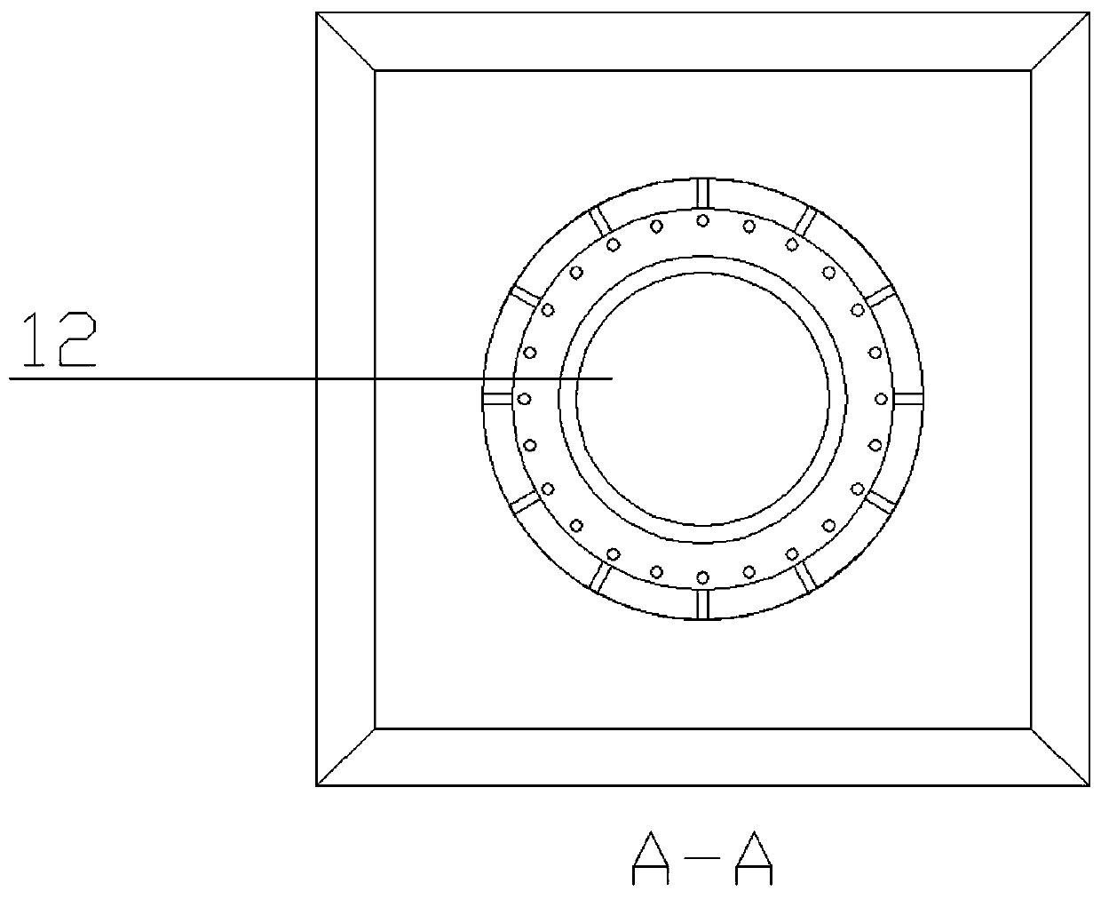
The invention discloses a radar antenna azimuth rotary table, and relates to the technical field of radar. The rotary table comprises an upper position rotary table, a middle pitching mechanism and alower position rotary table, wherein the lower position rotary table comprises a first gearbox and a first rotary table; the middle pitching mechanism comprises a bottom plate, a supporting side plate, a motor, a first rotating shaft, a driving gear, a driven half gear and a second rotating shaft; the upper positioning rotary table comprises a second gearbox, a second rotary table and an adjustinghandle. 360-degree dead-corner-free rotation is achieved through the upper rotary table and the lower rotary table, different control precision and adjusting handles are adopted for the two rotary tables, various experiments can be conveniently conducted on the antenna orientation, the pitch angle of the middle pitching mechanism exceeds 145 degrees, and the requirements of radar antenna experiments can be met.

Description

Technical field [0001] The invention belongs to the technical field of radar, and particularly relates to a radar antenna azimuth turntable, more specifically, a radar antenna azimuth turntable for testing. Background technique [0002] As a replay device in the test of related performance parameters of the antenna, the antenna test turntable is mainly used to support the weight of the antenna and control its movement, provide the required movement mode for the antenna, and give the position signal of the antenna through the angle measuring element. At the same time, data collection and analysis are performed on the tested antenna, so as to achieve the purpose of antenna performance test. In the early days when the antenna was used by people, its related parameters were low, which directly caused the performance parameters of the turntable to not be very high. Obviously, this is easier to achieve for mechanical and electrical control requirements. Then, based on the progress of ...

Claims


Application Information

Patent Timeline
IPC IPC(8): G01R29/10G01R1/04
CPCG01R1/04G01R29/10
Inventor 方期文
Owner WUHU LE CHUANG ELECTRONICS TECH CO LTD
Features
  • R&D
  • Intellectual Property
  • Life Sciences
  • Materials
  • Tech Scout
  • Unparalleled Data Quality
  • Higher Quality Content
  • 60% Fewer Hallucinations
Learn More